| Improved Transistor Circuit |
| PicAXE Ion Chamber |
| Best Ion Chamber Supply |
| Polonium Pen |
| Geiger Counters |
| Beta Particle and Radon Detector |
|
The Deep End PIN diode radiation detector |

(Earlier chambers may be viewed at techlib.com)
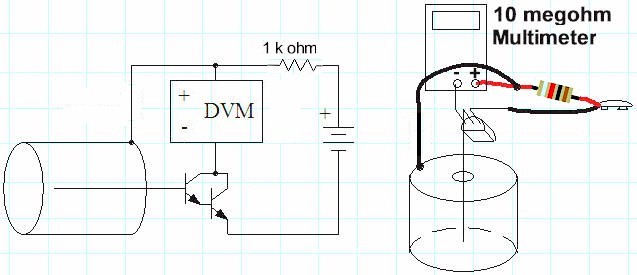
The single Darlington circuit could use more gain for detecting weaker sources but simply adding another transistor exacerbates the temperature drift problem. By building a differential amplifier with one side not connected, a temperature-compensated circuit results:
If the room temperature increases a little, both sides leak more current but the
voltage across the meter stays about the same. The 10k resistors are not
necessary but are included to protect the transistors from inadvertent shorts
during testing. Another 10k resistor between the battery voltage and the outer
can is probably a good idea in the event the can is shorted to the base of the
transistor. The schematic shows 12 volts but a 9 volt battery works fairly well.
The higher voltage sweeps the ions out of the chamber faster, before they have a
chance to recombine so the meter reading will be a little higher at 12 volts.
Two, 9 volt batteries in series are another alternative. The sensitivity is good
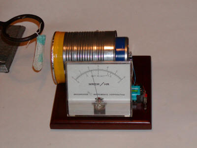
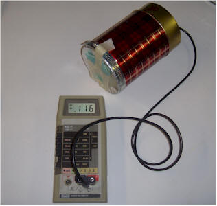
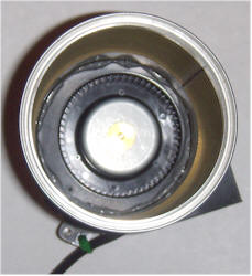
with just 9 volts; the photo shows the response to a radioactive mantle held
about an inch away from an aluminum foil window on the end of the chamber.
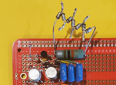
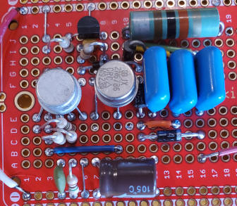
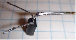
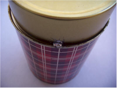
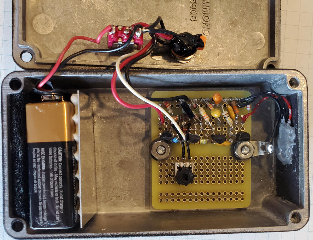
Construction of the chamber is similar to the earlier devices except the metal
end cap from a spool of resistors is used for the shield. This end cap
accommodates a multi-pin header that is used to hold the components and also
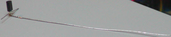
acts as a feedthru. The ion chamber sense wire is soldered directly onto the
base of the transistor and is suspended in air by the transistor without
additional support. It might be a good idea to use a plastic bead to hold the
wire more securely but this unit is well-behaved as-is. The meter should read
upscale slightly but, if it doesn't, try connecting the sense wire to the other
base and reverse the meter leads. If it still doesn't read a little above zero,
clean the transistors with acetone. If that doesn't work, try new Darlington
transistors since you probably have a leaky one. Hold a radiation source near
the aluminum foil window and the reading should quickly climb. The meter can be
a 1 volt digital panel meter or even a digital multimeter set to the 1 volt
scale. Another Petromax brand mantle with thorium was taped to a metal stand and
a video shows how a single mantle can
peg this meter. The circuit in the video has the zero pot mentioned
below.
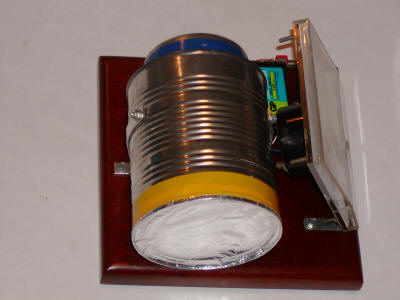
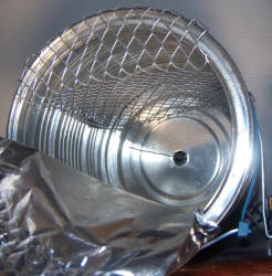
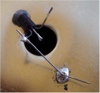
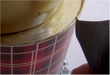
Since the original construction of this meter, a couple of useful modifications
have been made. A wire shelf was added to allow items to be inserted into the
chamber through a small hole in the foil without fear the item will touch the
center pin. (The foil is peeled back to reveal the expanded aluminum shelf in
the photo to the left.) Later I realized it's better to put the "shelf" at the
bottom so that the inserted item rests on the can with the screen simply acting
as an electrostatic shield and physical guard.
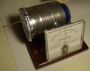
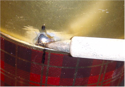
Additionally, a 100k potentiometer was connected across the battery and the wiper was connected through a 1 megohm resistor to the base of the Darlington that was originally not connected. This potentiometer becomes an effective zero control. The picture to the right shows the reading produced by a 2% thoriated tungsten welding rod inserted into the chamber. The meter was zeroed with the new potentiometer before inserting the rod. The reading climbs quickly to over half-scale and drops slowly back to zero when the rod is removed.
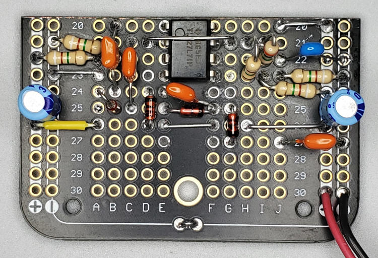
This simple radiation detector uses a PicAXE-08M microprocessor to measure the voltage drift rate on an ionization chamber's sense wire, eliminating the need for a high-value resistor. An electrometer-grade JFET is used to buffer the voltage on a sense wire inside the chamber, and a PicAXE microprocessor measures the rate of change of that voltage, periodically discharging the wire through the JFET's gate-source junction. This unorthodox way of discharging the ion chamber wire eliminates the need for a special, low-leakage switch, and takes advantage of the PicAXE's ability to use the same pin as an analog input or a digital output. Choose a PN4118 or PN4119 (or 2N equivalents) jfet.
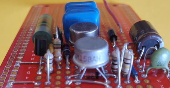
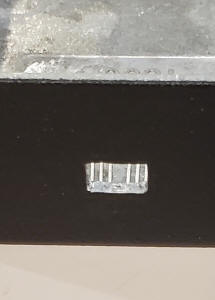
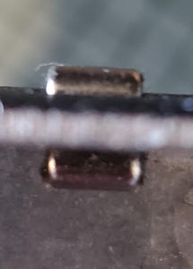
The ionization chamber and JFET circuit must be constructed with some care. The internal wire must be extremely well insulated from the can and most insulating materials are inadequate. I recommend styrene necklace beads:
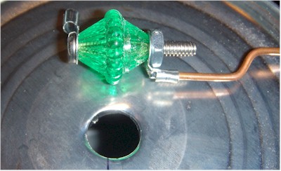
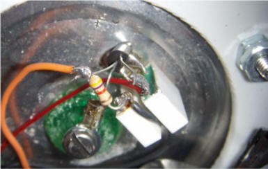
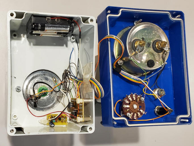
This large bead has a hole large enough for a 4-40 bolt that holds standoffs for the chamber's center wire, and for connection to the JFET gate. The can is heated and the bead is pressed into the hole, melting into place as it seats. With a little effort, the bead will be locked into the hole, once the metal cools. You may add epoxy to hold the bead, but keep the epoxy away from the conductors (see close-up below). Make sure to cut the copper center conductor (just a piece of 14 AWG solid copper wire) about a half inch short of the can opening, so that the foil window won't accidentally touch it. Choose a can about 4.5 inches tall, with a diameter of about 4 inches. The JFET is mounted on the outside, bottom of the can as seen below. The two white blocks are low-value capacitors with at least a 100 volt rating and they are simply there to support the parts, and are not shown in the schematic. The white block capacitor to the left holds the drain lead and a wire from +9VDC. The white capacitor to the right holds the 47k resistor that connects to the FETs source. Note the barely visible black wire that snakes around to connect the top terminal of that capacitor to the circuit ground. Remember, the can will be biased to 50 volts and can't be used for ground. Ordinary insulated standoffs or a terminal strip will also work, but make sure the gate wire doesn't touch them (or anything but the solder terminal on the plastic insulator). Many readers have had troubles with these chambers because they simply don't believe that "insulators" leak, but they do! Note that I rearranged the wires so the red wire doesn't pass so near the gate connection; nothing can touch that connection, not even wire insulation. Sometimes I'll add a 1 megohm resistor in series with that gate connection to protect the FET from inadvertent shorts to the can and it's not a bad precaution. A shield is necessary as is seen in the photo to the right.
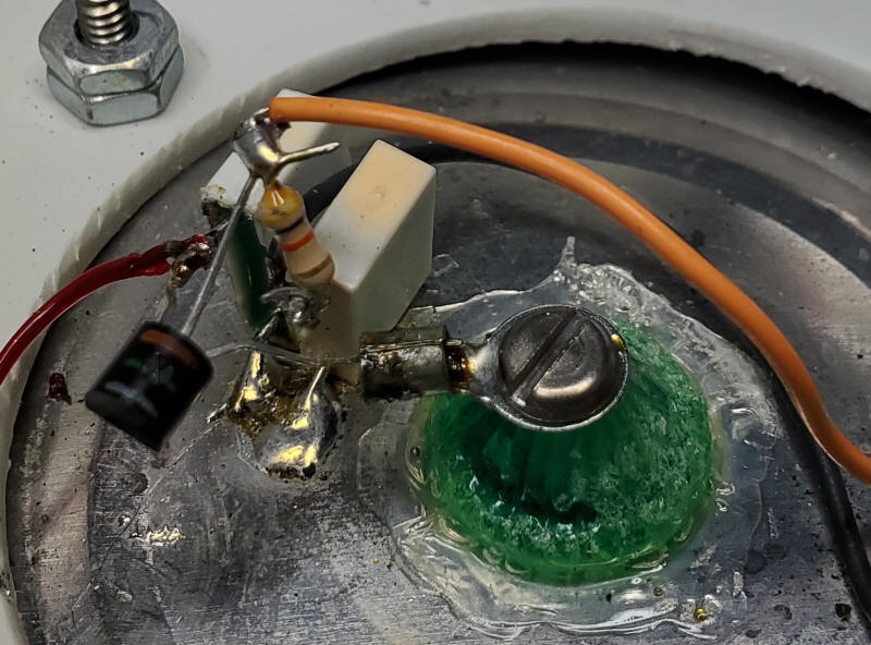
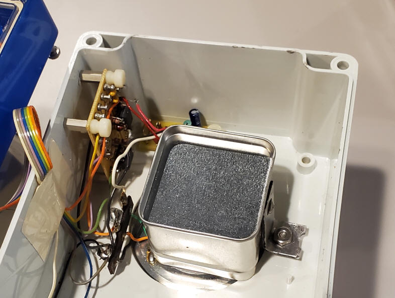
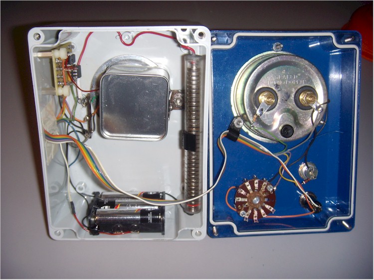
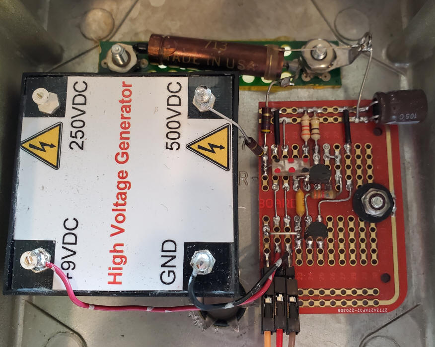
It is important to have a shield over the JFET and resistor. Simply tack-soldering a little mint can over those parts is sufficient. Mine is held in place by a bracket soldered to the shield can and mounted on one of the bolts holding the chamber to the case. The photo below shows the original long battery pack (homemade 50 volt battery made from surplus alkaline cells), but three or four 9 volt rectangular batteries will work fine or a simple circuit to generate 50 volts. I've replaced the original 50 volt battery pack (seen below) with the generator from Frankenstein's Dosimeter (small board at the bottom in the second photo at the beginning of this article). That circuit is shown directly below (ignore 6 VDC, it runs fine on 4.5 VDC, too). Add a 1 megohm in series with the output to the can and a 10uF cap from that chamber can to ground. I didn't! But I recommend it to reduce the noise coming from the generator.
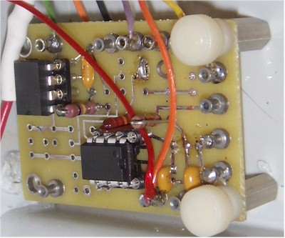
I used the older CA3160 op-amp as a meter driver, but any low-voltage "rail-to-rail" op-amp will work. I used my own prototyping board for the PicAXE, but any construction technique is fine. The two yellow capacitors on the PicAXE board are left-overs from an unnecessary voltage regulator.
Here's how it works:
Positive ions in the chamber produced by radiation (mostly beta particles) are
attracted to the center wire, where they steal electrons on contact. That
process produces a positive current that charges the capacitance of the wire and
JFET gate in a ramp fashion. The JFET's source follows the gate voltage (with
about 1 volt of positive offset), and the PIC measures the rate that voltage
changes. The PIC first resets the chamber by momentarily pulling the source of
the JFET to ground. The chamber wire discharges through the gate diode to within
a few hundred millivolts of ground. Then the PIC releases the source and
measures the voltage. It waits a fixed amount of time and makes another
measurement. The two measurements are used to calculate how fast the voltage is
changing, and, therefore, how much radiation is striking the chamber. The
process automatically repeats, flashing the LED each time. The value to display
is output as a variable duty-cycle pulse that is filtered and buffered to drive
a meter. I chose an old-fashioned analog current meter, but other meters will
also work. The PIC may be programmed to send the data back to a computer via the
serial port, too.
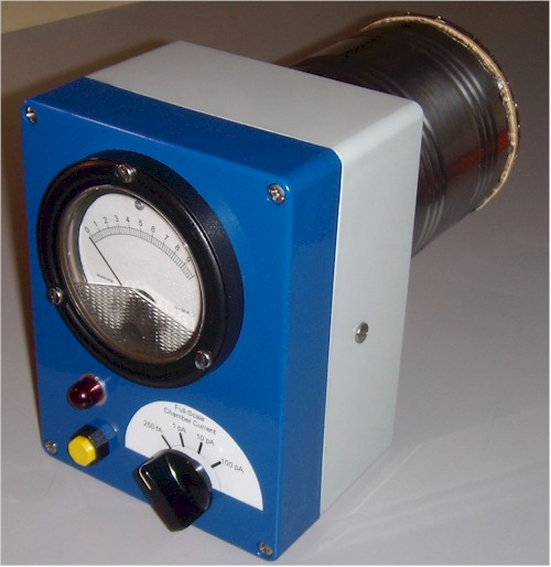
The four-position switch selects one of four voltages to send to the PIC to
select the range. The most sensitive range is about 250 fA, full-scale, and that
was experimentally determined by connecting a high-value resistor to the chamber
wire and calculating the rate of change of voltage to determine the capacitance
(about 10 pF). It's an approximation, but relative readings are usually all
that's interesting. If you build you chamber like this one, the capacitance will
be quite similar. The less sensitive ranges are 1, 10 and 100 pA. It takes 10
seconds per reading on the most sensitive scale and only a fraction of a second
on the least sensitive scale.
View a short clip with the meter on the 1 pA scale, detecting a thoriated
lantern mantle. Note the delay as the PIC measures the rate of voltage drift
(about 5 seconds on the 1 pA scale).
The program below is quite simple and short, leaving lots of room for
modifications and additional features. Don't study the code if you don't care
for microprocessors. Get the free editor from picaxe.com and figure out the few,
easy details to get this program into the chip. Then you have a "custom" IC.
main:
high 0 'turn on LED.
w4=10000 ' set delay to 10 seconds.
w5=8 ' set multiplier to 8 (increases reading by 8). These set the 250 fA scale.
readadc 1,w3 ' read the 4-position switch voltage (will be near 0, 85, 171, or
256).
if w3 >40 then ' see if switch is above first position.
w4=5000 ' set delay to 5 seconds.
w5=4 ' set divisor to 4 (these two mods reduce the sensitivity by 4 for the 1 pA
scale.
endif
if w3 > 125 then ' see if switch is above second position.
w4=1000 ' set delay to 1 second.
w5=2 ' set multiplier to 2 (reduces the sensitivity by 10 for 10 pA scale).
endif
if w3 > 210 then ' see if switch is in fourth position.
w4=100 ' set the delay to 100 milliseconds.
w5=2 ' set multiplier to 2 (reduces the sensitivity by 10 again for the 100 pA
scale).
endif
low 4 ' pull the source of the JFET low
pause 300 ' keep it low for 300 milliseconds.
let dirs = %00000100 ' set the necessary pins back to inputs.
pause 50 ' let the voltage stabilize.
low 0 'turn off LED
readadc10 4,w0 ' read the JFET source voltage.
pause w4 ' wait for the selected delay time.
readadc10 4,w1 ' read the JFET source voltage again.
w2 = w1-w0 ' calculate how much the source voltage changed during the delay
w2=w2*w5 ' scale the result by the selected multiplier.
if w2>1000 then ' sometimes the voltage will drift negative, causing a
full-scale reading.
w2 = 0 ' these commands reset the meter to read zero when that happens.
else
endif
If w0>512 then
w2=800 'peg the meter because the first reading shouldn't be so high - must be
lots of radiation
endif
if w2 > 800 then ' My meter pegs at about 700, so this limits the current a
little higher.
w2 = 800
else
endif
pwmout 2,off 'reset the pwm from last pass.
pwmout pwmdiv4, 2, 249, w2 ' set the pwm output for driving the meter.
goto main ' wash, rinse, repeat.
' There's plenty of room for more of a program, if desired.
' Copy all this text, paste it into the editor, and click on "syntax" to check
it.
I've detailed many ways to generate higher voltage for ion chambers but this is probably the best way if you have plenty of power supply voltage; as the supply voltage goes down the number of necessary diodes goes up. Thanks to the out-of-phase drive each diode adds Vcc minus a diode drop to the output. The micro-power op-amps from the TLC27 family (any will work) draw under 15uA total when running on 15VDC and generating 55VDC (assuming no load current but zero current is a pretty good approximation for an ion chamber). Adding a couple diodes and caps allows the circuit to run on only 9VDC while generating 48VDC with similar current drain. A 9 volt rectangular battery would last for years without a power switch. AAA cells might last a decade. If you like micro-power circuits buy a handful of these currently produced op-amps before they disappear! Other op-amps will work with more power consumption but be sure the op-amp can handle the desired battery or power supply voltage. Also make sure that the op-amp can tolerate significant differential input voltage difference; many can't due to protection diodes on the inputs.
The output of this circuit should drive a relatively high-value resistor followed by a non-polar cap to ground, typically a 1 megohm resistor and 10uF film capacitor connected directly to the chamber can and to the battery negative. Ion chambers need very little current and this low-pass filter will reduce the AC signal from this circuit that appears on the chamber can.
Recent events point to the need for a simple device for testing cocktails and beers for excessive quantities of polonium. The Polonium Pen is a pocket-sized ion chamber with LED readout that is perfect for the job. Simply hold the Polonium Pen over your drink and, if the LED lights up, order something else.
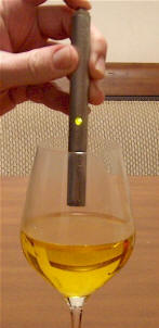
The circuit is similar to the single transistor detectors above and only requires two Darlington transistors, an LED, and one or two resistors along with a battery, power switch and tiny homemade ionization chamber. This prototype was a bit difficult to build, but the pen may be built in any number of ways as long as a couple of critical requirements are met. The wire probe sticking into the ion chamber must not touch anything that is ever-so-slightly conductive, not even most glasses, and the electronics must be surrounded by a metal package to shield it from stray electric fields. Because the ion chamber is so small, the LED will only light in the presence of a significant amount of radiation, most likely alpha particles. The prototype will light up brightly when held near the Americium bit in a smoke detector's ion chamber and a polonium-laced drink should produce the same reaction. But most radioactive sources the experimenter is likely to have will not produce any response at all, placing this in the novelty category for most of us, fortunately. The LED also comes on when the button is first pressed for a couple of seconds before fading out, hence the lit LED in the photo! This "feature" insures that the pen is working properly.
The first prototype required a high-value resistor (66 megohms) across the emitter-base of the PNP darlington to get the LED to go out but the second unit didn't need one, possibly due to superior insulation of the sensor wire. A value as low as 22 megohm is fine and even lower is probably OK for detecting really "hot" drinks! The prototype's ion chamber is made from a 1.5" long piece of 11/32" dia. brass tubing and any similar size will work. The first probe wire was a pin from one of those "pin art" bed-of-nails toys. The insulator in the photo is a glass necklace bead, but it turned out to be far too conductive. It was replaced with a similar sized plastic bead. The new bead was slightly too large for the brass tube, but by heating the tube with a soldering iron while pressing the bead into the tube, the bead was easily cut down to size. (Place masking tape on your fingers to prevent burns!) The bead was easily popped back out with a screwdriver. A nail was glued into the bead with a little length at the head end for making the transistor connection and then the bead was glued into the brass tube. Another bead was temporarily slipped into the other end to hold the nail in the center of the tube while the glue dried. I switched to a nail for the probe because it fit in the new plastic bead better. Tin and clean the nail before inserting in the bead, especially if steel flux is needed. Later, solder the base lead on quickly; the plastic beads melt easily. The epoxy technique mentioned earlier will also work well.
A fine mesh screen was wrapped over the open end of the chamber to keep out wind currents and electric fields. Rolling the screen between the fingers makes it conform to the shape of the tube nicely. Solder the screen to the tube in one spot. Some screen materials may require steel flux, but the screen should be tinned with the flux and then washed with hot water and detergent before placing it on the tube; that flux is highly corrosive! Copper screen is recommended; the screen shown is plated copper and it takes solder nicely. Make sure the sensor wire doesn't touch the screen and is fairly well centered in the tube (not critical). The circuitry was constructed using point-to-point wiring and is held in place by the base wire soldered to the nail's head and the emitter of the PNP soldered to the brass tube. One end of a battery connector was fashioned from another glass bead (long, dark tube on the right in the photo below) and a copper-plated nail. A white plastic bead was used to cover the end of the copper nail where the wire connects.
Some thin Kapton tape was carefully added to insulate the circuit from the outer tube but no tape was allowed to touch the NPN's base lead. Even electrical tape is too conductive. The outer tube was fashioned from 1/2" stainless steel tube, but copper would have been much easier to machine. The assembly was placed next to the tube to locate the hole for the LED, and a cotton swab was marked for depth with a black marker for applying epoxy to the inside of the tube to hold the glass bead battery terminal. The swab was dipped in epoxy, inserted up to the black mark, and the epoxy was swabbed along the inside wall of the outer tube. After the epoxy was applied to the inside of the steel case, the assembly was slid into place (bead first) and the LED was positioned to face out the hole. After the epoxy set, conductive silver paint was gingerly applied to the edges of the screen to hold the ion chamber in position and to ensure a good electrical connection to the outer tube.
The other battery contact was made from a spring stolen from a AA cell battery holder fastened to a 1" steel standoff. The screw fits inside the spring and holds the narrow end of the spring to the standoff. The wide end of the spring friction fits in the steel tube to make contact. It is nicely centered by the tight fit and doesn't touch the center contact of the battery. When the button is pressed, the head of the screw makes contact with the battery's positive terminal, completing the circuit. The standoff "button" is held in place by a homemade nylon bushing that screws into the steel tube. (Threading the stainless steel was difficult! And fashioning the bushing from a nylon rod was no picnic.) The end of the standoff that protrudes was ground down to match the steel case after cutting off enough to eliminate the threaded hole. The steel case was given a coarse sanded finish, too, to hide all the scratch marks from the threading process! The brushed finish actually looks nicer than the original shiny finish and it hides fingerprints. This isn't the easy way to build such a pen but it gets the idea across.
A tiny 10A 9 volt alkaline battery was installed and the threaded nylon bushing was tightened. A little clear epoxy fills the LED hole and the pen is complete:
Every spy and "diplomat" should have one!
Note: It has been suggested that this pen might not detect polonium in a drink
at concentrations that are lethal. Polonium emits copious quantities of alpha
particles, really a mind-bending amount, but alphas cannot travel through a
liquid. They barely make it through a few inches of air. So, the pen will only
receive alphas from the very surface of the liquid. Polonium is ridiculously
toxic and it doesn't take much to kill. On the other hand, polonium really pours
out alphas. Bottom line is I don't really know if it works and I'm fresh out of
polonium to try. But, seriously, this pen will detect the americium bit in your
smoke detector and that's all you will likely encounter that can light the LED.
It is not a general-purpose radiation detector.
These circuits employ high voltages and can cause dangerous shocks! Do not build these devices unless you are experienced and qualified to work on high voltage devices. Avoid charging a high-value, high voltage capacitor with the generators below. But even a small capacitor can cause you to jerk your arm back, spilling your mug of coffee all over your paperwork. Umm, for example. Discharge before touching! I now leave a clip lead attached to ground with a 100k resistor clipped to the end. I just touch the resistor to the output of the generator for a couple seconds after the power is removed.
A good place to start with your Geiger counter is to select a high-voltage generator for the Geiger-Mueller tube. I have a few transistor designs on techlib.com and there are good ones elsewhere on the web but the circuit below is now my favorite. The regulation is precise and accurate using ordinary parts and the power consumption is quite low, 1mA for a typical application. (To be fair to my older circuits, they qualify as micropower once the voltage is reached; they really cut back. But most Geiger counter applications don't need micropower, just low power.)
The modification to the right shows how four more diodes may be added for an output voltage of 1000 VDC for the same voltage swing on the drain of the FET. After the first doubling, you add two diodes and two caps for each additional voltage step (times 3 would require 5 diodes and 5 capacitors). Three multiplication steps to get 900 volts would require a MOSFET that can handle 300 volts on the drain. I've shown four multiplication steps for voltages up to and somewhat over 1000 volts; just adjust the 510k resistor to get the desired voltage. Note that the top caps pass the AC from the drain to each stage and the bottom caps (below the diodes) charge to a DC value. Those DC voltages can all be used within the power limits of the circuit. As an example, a longer multiplier string driven by a lower initial voltage could bias the dynodes on a photomultiplier tube. The DC caps can be connected to ground rather than the previous DC capacitor but the voltage rating requirement goes up towards the output; these caps are in series and share the voltage handling burden. For other applications an additional low-pass filter could be added directly at the output consisting of a fairly high-value resistor and a high-voltage capacitor connected to ground. Remember, the bigger that cap is, the more dangerous the circuit!
The 5 volt version (works as low as 4 volts) will work fine at 9 volts. I show it to emphasize that the lower voltage may require a rail-to-rail output op-amp and a MOSFET that will turn on reliably with lower gate voltage. LM358s or LM324s (quad version) are very common and great for a 9 volt version. Power consumption is quite low so a 9V rectangular battery will last a long time.
The leftmost op-amp is connected in the common square-wave oscillator configuration operating near 3kHz. The FET is alternately shorting the inductor to ground then disconnecting the inductor at that rapid rate. While shorted to ground, current in the inductor rises and when disconnected that current makes a left turn and flows through the first diode and capacitor in the Cockcroft–Walton voltage multiplier. The voltage will rise as high as necessary to keep that current flowing until the energy stored in the inductor is dissipated. If the process weren't stopped or limited, the voltage would climb high enough to cause a MOSFET avalanche breakdown. Most MOSFETs for power switching can take it but the efficiency of the circuit will be poor. Before that happens, the other op-amp compares a divided-down version of the first DC voltage in the multiplier to a low-voltage reference and when the voltage is high enough, the op-amp stops the oscillator by raising the voltage on pin 2 via the 1N4148 diode. Once that limiting process starts, the previously free-running oscillator becomes a pulse generator triggered by that feedback signal; as the load increases, the pulses will speed up, holding the output voltage steady. This circuit can drive a 10 megohm DVM directly (50 microamperes at 500 volts) but that's a lot more current than is needed for a Geiger tube. But it's convenient to be able to measure the output voltage directly. However, it can also bite you a bit harder than my earlier circuits; so take care! When measuring the voltage with a DVM the circuit will draw about 10mA and that will drop to about 1mA when driving a Geiger tube.
Parts:
The voltage reference may be just about any voltage with a proportionate change in the value of the 510k resistor. You could also use a regulated voltage, say 5 volts, if available. But you could also simply divide down the 9 volts with a couple resistors (perhaps 1Meg from 9 volts and 150k to ground); the voltage will vary a bit as the battery dies but Geiger tubes aren't all that sensitive to voltage variations. Just set the voltage a little on the high side with a fresh battery.
The 1N4937 rectifiers are fast recovery types and they're about 30% more efficient than the slower 1N4007 at 50uA but I didn't see a significant difference at low current so don't hesitate to use a slower high-voltage rectifier if that's what you have.
Choose an inductor with some resistance, say between 30 and 100 ohms, the low end avoids startup problems and much higher than 100 ohms might limit the output current sufficiently to prevent a simple voltage measurement with a DVM. (You can always add a resistor in series with your DVM to reduce the current. Four, 22 megohm resistors in series are nearly perfect to make a 10-to-1 probe, 90 megohms total being perfect.)
I was happy to see that 100 megohm resistors are readily available for a low price but four or five 22 megohm resistors in series would also work. The bottom 510k resistor would be selected to get the desired output voltage. The high value near 100 megohms saves battery current but it's also low enough to load the first multiplier stage a bit, a requirement for good regulation at the output.
The MOSFET can be any one of a bewildering number of choices with a voltage rating of 400 volts or more. Select one with a few ohms of channel resistance and lower current rating, perhaps less than 1 or 2 amps (smaller die with less capacitance than a monster from a powerful switching regulator). I chose an older metal can part for 9 volts simply because I have them and I like the way older circuits look! The 5 volt version uses a newer MOSFET that turns on with a lower gate voltage allowing the circuit to work down to 4 volts. This whole circuit could be built with surface-mount parts with only the inductor and supply capacitor being of significant size.
It's hard to beat the common LM358 or LM2904 for this application running on 9 volts. The 5 volt version benefits from an op-amp that can swing rail-to-rail on the output, ensuring it can stop the oscillation. Make sure the chosen op-amp can tolerate significant differential voltage on the inputs of more than 1/3 the power supply voltage; many can't due to internal protection diodes across the inputs. Both the LM358 and LM6582 can tolerate large differential voltages. (Look at the "Maximum" ratings on the data sheet.)
Note that the feedback is necessary to constrain the voltage. If that part of the circuit isn't working due to a mistake in wiring or some leads are momentarily shorted while probing around it's quite easy to lose some vulnerable MOSFETs or especially the capacitors to voltage breakdown. (Note that most, if not all power MOSFETs can tolerate a lot of over-voltage abuse! They'll avalanche but not be damaged as a result by the small energy involved here.) But the capacitors are vulnerable, too. Being overly cautious, I tack in a temporary string of zener diodes to limit the voltage while working with the circuit. Connect the cathode to the drain of the MOSFET and the anode to the positive power supply voltage. The zeners will cause a bit of additional supply current but they're temporary. I used seven 51 volt zeners in series:
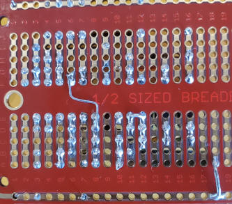
For better grounding, I found a spot in the middle of the board where I could run the positive voltage from the top "+" rail to the grounded electrolytic cap at the bottom (row 7). These protoboards suffer from a lack of ground plane so keep the traces short where the supply bypass capacitor goes. It wouldn't hurt to have a couple more with 0.1uF caps wired similarly but it seems to work fine, as-is. I potted mine simply because I have the materials (totally unnecessary) :
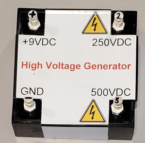
Note that the 250 volts on the first DC capacitor may be utilized, too. (DC caps are underneath the diodes in the schematic.)
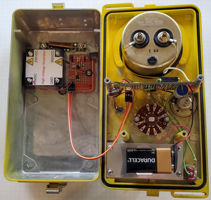
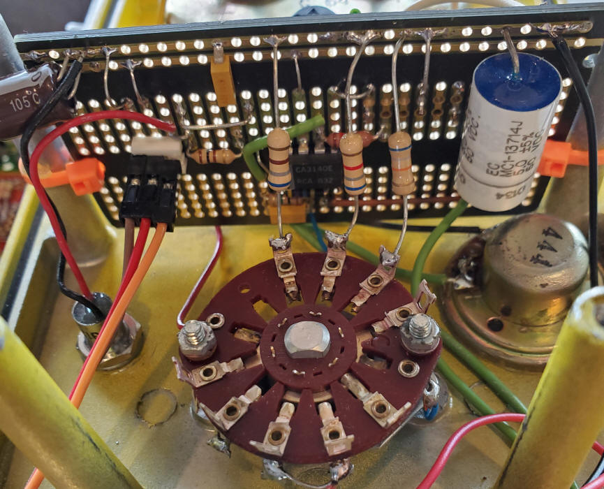
Here's a complete Geiger counter circuit utilizing the voltage generator above. It features a simple pulse stretcher that provides a 9 volt pulse about 300uS wide with good current capability, sufficient to drive a small speaker, LED and averaging circuit for a meter. The speaker should be a higher resistance type, above 30 ohms. A suitable speaker may be salvaged from abandoned, cheap headphones. The averaging circuit has slow, medium and fast settings but the slow setting is very, very slow and may be left out. In that case use an ordinary toggle switch to select either 1 megohm or 10 megohms. The op-amp should be a CMOS type with input ground sensing and be able to swing near ground on the output. I used the CA3140 but added the recommended zero offset trimmer (a 10k potentiometer connect across pins 1 and 5 with the wiper going to ground). Zero the meter with the switch in the 100 CPM position and with a clip lead shorting the 4.7uF capacitor to ground. A chopper-stabilized op-amp would be a good choice, too (LTC1050, TLC2652, or newer parts). The pulse stretcher circuit is located near the Geiger tube and only three low-voltage wires are needed to connect to the rest of the circuit. The circuit draws about 2mA when the count rate is low so a 9 volt battery will last for 10 days of continuous operation.
Note: I'm getting huge pulses out of the tube but some tube specifications I've seen suggest much smaller pulses from other tubes. If your circuit doesn't trigger, try a 1 megohm to the tube (horizontal 4.7 megohm) or just a jumper; most other circuits don't have the resistor in series with the tube. I like the resistor because mistakes happen when building such a circuit. I don't know what happens if the tube is accidentally hooked across the high voltage supply without any resistor but it might not be good! Some older tubes have lower recommended anode resistors. I see 1 megohm used in older Geiger counters with tubes needing 900 volts (type 6993, for example) and the tube connects directly to a much larger capacitor that feeds the circuit. I'm trying to be more gentle with my tube. LND recommends a 4.7 megohm resistor for the 713 and I added the series resistor to make the voltage source to the tube more resistive (no large, charged coupling capacitor ready to dump energy into the tube). Bottom line: leave out the horizontal 4.7 megohm if you like. Just don't short the tube directly to the 500 volts.
The circuit could be built quite small but I have a huge stash of the old CDV717 survey meters that make great project boxes. For this project I've eliminated the bottom case that houses the ion chamber and extension cable:
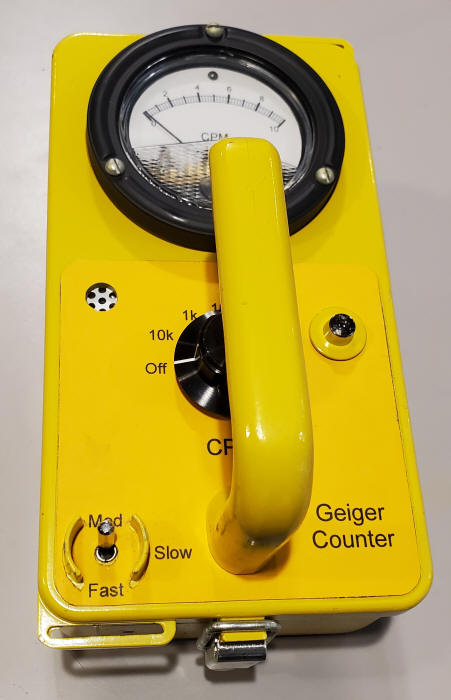
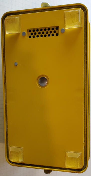
The tiny tube is glued to a small piece of circuit board drilled with a hole pattern to let in more of the weaker beta particles. The toggle switch to the bottom right isn't long enough for the threads to come out the front so I simply epoxyed it in place.
These meters (with the black bezel) can be opened and the scale modified. In some instances it's practical to flip the plate over to apply the new scale to the bare aluminum back. I use an old version of TurboCad that will only work on Windows 7 or earlier to make my new scale but most hobbyists have their own way of doing the same task. I printed my label on yellow/orange paper and sprayed it with Krylon clear coat. In the past I've used a light coat of the Krylon followed by a thicker coat of urethane (really tough stuff).
I've used a Corning glass capacitor for the 22pF. Make sure to choose a capacitor with a high breakdown voltage, typically 1000 volts. The 4.7uF (5uF in mine) capacitor may be any film type but not an electrolytic. I suppose ceramic will work, too. My LED has a built-in resistor in case you are wondering where it is. A single pole, 3 position range switch will work if you prefer to have a separate on/off switch. And note that I ended up switching the battery's positive terminal instead of the negative terminal as the schematic shows; either is fine.
This ionization chamber beta/radon detector is designed to be easy for the student or hobbyist to build and use. It can form the basis for a variety of experiments for Science Fair competitions, class projects, conversation pieces, or simply satisfying scientific curiosity. Despite the extreme simplicity, the chamber can detect surprisingly low levels of radon by detecting the radioactive decay of "radon daughters" produced when radon gas decays. The decay chain produces beta particles that make it through the foil window yet cause significant ionization within the chamber.
Ordinarily, radioactive materials around you are safely bound up in solids, like trace amounts of radioactive isotopes of uranium, thorium or radium, trapped in the concrete and earth beneath your feet. But these radioactive materials "decay" into lighter elements, emitting energetic sub-atomic particles in the process. One of the lighter elements in the chain of decay is radon, a radioactive, noble gas. Since radon is a noble gas, it is chemically inert and doesn't stay bound in the solid the way it's parent did. It diffuses right through solids and ends up floating freely in the air. Being a noble gas, radon is fairly harmless, itself. You breath in some radon with every breath but then you breath it right back out, since it isn't chemically active or electrically charged. But radon has a short half-life of only about four days, meaning that about half of it will decay within four days, producing new, even lighter radioactive isotopes of other elements like polonium, lead, and bismuth. Those isotopes keep decaying, until a stable isotope of lead is reached. These radon "daughters" are not noble gasses like radon, they are usually ionized when they are produced, and they will readily stick to anything nearby, like healthy lung tissue. They typically have an even shorter half-life than radon and quickly decay inside the lung, kicking out energetic alpha and beta particles that can cause tissue damage and potentially trigger lung cancer. This unfortunate chain of events is due to the decay chain including a noble gas! Radon gas is considered to be the second leading cause of lung cancer, even though her daughters are the real culprits.
Radon daughters will stick to just about anything they encounter, so they are easily collected by drawing air through a dusting cloth with an ordinary fan. After collecting the daughters for about an hour or two, the radiation being emitted from the cloth due to the further decay of the collected radioactive isotopes can be measured with a simple ionization chamber made from an empty coffee can, a single Darlington transistor, and a digital voltmeter. The deceivingly simple ion chamber is quite sensitive and can detect radon daughters in buildings with radon concentrations below the "action level" recommended by health authorities.
A simple ionization chamber is nothing more than a metal can with a wire inside. When a radioactive particle passes through the air in the chamber, many of the molecules of air are ionized, having electrons knocked loose from the outer atomic shells. Applying a positive voltage on the outer can relative to the internal wire, causes these ions to be attracted to the wire and the free electrons to be attracted to the interior wall of the can. This movement of charge is a tiny current that may be amplified to detect the rate at which ions are being generated, and thereby the rate that radioactive particles are passing through the can. The simple chamber described below is capable of detecting extremely tiny currents. When a digital DVM, with a 10 megohm input resistance is on a voltage scale, 10 millivolts on the meter corresponds to 1 nA flowing in the meter (10 mV / 10 megohm = 1 nA). Assuming the gain of the transistor is about 30,000, the base current is 10 nA / 30,000 = 33 fA or 0.000000000000033 amps, a very tiny current, indeed! A single femto-ampere is the flow of 6,240 electrons per second so a change of 10 mV on the meter represents a couple of hundred thousand electrons being liberated every second. There's quite a lot of activity going on in that small volume of air when you place the radioactive sample in front of the foil window and the reading climbs several tens of millivolts. The chamber will be detecting mostly beta particles. Alpha particles can't make it through the aluminum foil window.
First, acquire an empty metal can about 5 inches tall, with a 4 inch diameter to be used as the ionization chamber. Typical cans include a small coffee can, a baby formula can, or a holiday snack tin. The size is not critical. Also find another short tin with a slightly smaller diameter with a height of 1.25 inches or a little more. These tins are commonly used for hard candy. This smaller can will shield the electronics. It is necessary to shield the circuit from external electric fields.


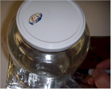
Find the center of the bottom of the ionization chamber can. A simple way to find the center is to measure the diameter and divide by 2 to determine the radius. Now, use a fingernail pressed against a ruler to establish the radius, press the fingernail against the can, and draw a few lines from different directions to mark the center. The center isn't critical.
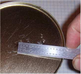
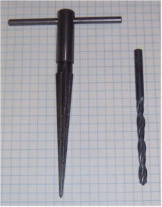
It can be difficult to drill a clean hole in the thin metal and a satisfactory alternative is to drill a smaller hole and use a hand reamer to widen the hole to about 1/2 inch diameter. The excess metal will form a short, ragged tube extending into the can instead of breaking off in bits but the hole will be smooth and round on the outside.
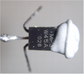
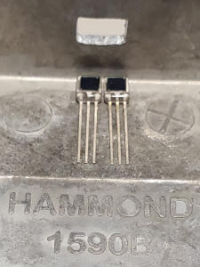
Bend the base lead (middle pin) of the MPSW45A Darlington Transistor at a right angle, extending away from the flat side of the body. Solder a piece of solid, 22 or 24 AWG bare wire to the base lead. Cut the bare wire to be shorter than the ion chamber can by 3/4 inch.
Apply a small amount of epoxy to the top end of the transistor, keeping the epoxy well away from the leads. IMPORTANT! Don't get the epoxy on the center lead! Other NPN darlington transistors will work well in this project but the MPSW45A has an extra-tall package, making it easier to keep the epoxy away from the legs. Pass the long wire into the can and press the flat side of the transistor against the outside bottom of the can, allowing the epoxy to spread onto the can. You may solder a temporary wire to the can to help hold the transistor while the epoxy cures. Check to make sure the center lead is free from any epoxy.
Solder a 1k resistor in series with the positive (red) battery snap lead and cover it with heat shrink tubing or electrical tape. This resistor may be left out, but accidentally shorting the transistor base lead to the can will destroy the transistor. The resistor is a good idea!
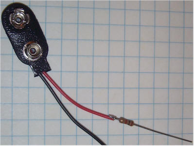
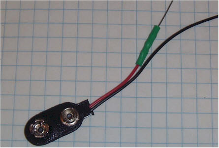
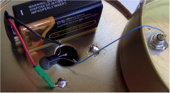
Apply some double-sided foam tape to the edge of a 9 volt rectangular battery on the side that will result in the wires from the battery snap coming out on top. Stick the battery to the bottom of the ion chamber can near the hole. (The battery may also be glued into position. A new battery might last over 10 years.) Connect the positive lead (or optional resistor) directly to the can. Connect the negative battery lead (black) to the emitter of the transistor (left lead with the flat face down and the leads pointing away from you). Connect a thin, flexible 3 inch wire to the remaining collector lead (right lead with the flat face down and the leads pointing away from you). This should be a thin, flexible wire so that it doesn't pull on the transistor very hard as you move things around. 30 AWG "wrapping" wire is ideal.
|
|
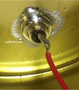
Drill a 1/4 inch hole in the bottom of the short can near the edge. The location is not critical. Use fine sandpaper or a rotary tool to remove the enamel coating around the hole on the inside of the can so that the washer will make electrical contact. Mount the RCA phono jack in the hole. It is hard to tighten such a connector in thin metal without damaging the connector or bending the can. So, optionally, snug it up reasonably tightly and solder the nut to the can and threads to keep it in position. Other connector types will work. Simply running the wire through the hole is adequate, but you will need an additional wire for the can connection.
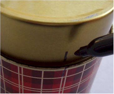
Position the two cans together making sure the connector doesn't hit the battery and the wire stays away from the center lead of the transistor. Holding the two together with a good orientation, mark across them with a marker in two or three locations. Sand off the finish on both cans near the marks with fine sand paper. You just need to expose the bare metal so that solder will adhere. Connect the battery snap to the battery, and tack solder the two cans together, using plenty of heat and solder. The circuit draws virtually no power so the battery will last many years, essentially its shelf life. When soldering the cans together, let the iron sit several seconds to heat both cans. Right before removing the heat, add a little more solder and the fresh flux will brighten the joint.
Find a circular object with a slightly larger diameter than the ion chamber can and use it to draw a circle on a piece of aluminum foil. Sand the paint off the lip of the can so that the aluminum foil will make electrical contact. You may try to use a rubber band or tape to affix the foil but it is difficult to let go of the band without destroying the foil. After you destroy a few pieces and learn a few new words, try a large pipe clamp. Make sure the foil is pulled tight against the sanded lip of the can so that electrical contact is made.
Add rubber feet to whichever side looks like the bottom (not critical). Large, adhesive-backed rubber feet can be cut in half with heavy scissors or tin snips. The resulting thin feet will fit to the curved can better.
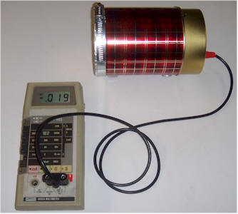
The chamber is finished! Connect it to a digital voltmeter set to the 1 or 2 volt scale. The reading should drop to a few tens of millivolts, depending on the room temperature. In the cool laboratory, the background reading is 19 millivolts. Taping an older thoriated lantern mantle to the foil window increases the voltage reading to 116 mV! Remember, most newer lantern mantles don't contain thorium.
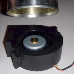
It is easy to collect radon daughters, those dangerous radioactive isotopes that form when radon gas decays. Simply draw air through some sort of material and they will rapidly collect. The photo below shows a simple collector that is easy to build.

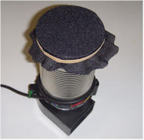
The collector consists of a DC-powered squirrel cage fan drawing air through an empty soup can with some filter material secured over the opposite end.
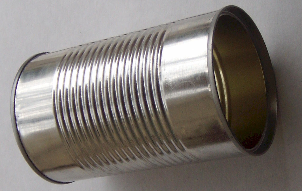
Cut off both ends of an ordinary soup can and remove the label:
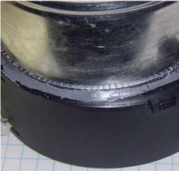
Affix the can to the intake of a squirrel cage fan using epoxy. Apply a bead of epoxy to the lip of the can, making sure to leave no gaps, and seat the can on the fan's intake, making sure no epoxy drips into the fan:
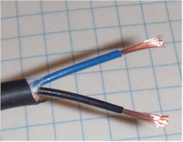
The can may be offset from center a little, as long as the intake is completely covered. After the epoxy has had plenty of time to cure, cut any connector off the end of the fan's cable and remove some insulation from the red and black wire:
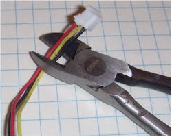
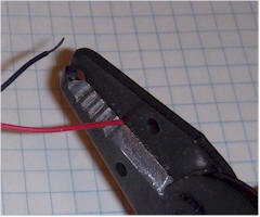
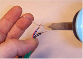
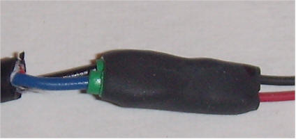
This fan has an unneeded yellow sense wire that was cut short. Cut off the end of the power supply cable and strip off some of the outer insulation:
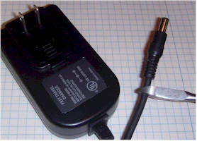
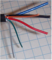
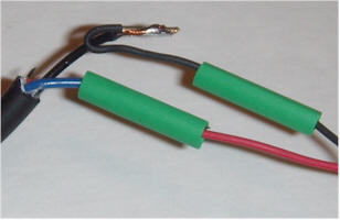
Some power supplies have lots of wires, but most are not connected. Often the unused colors will pull right out of the cut off connector, but the most reliable way to find the right two wires is with a voltmeter. Plug in the power supply and find the two thicker wires that have the power supply's rated voltage across them. Note the polarity and unplug the supply. Strip those two wires and connect them to the fan with red going to positive and black going to negative. Plug in the power supply to verify the fan spins. For the supply shown, the blue wire from the supply was positive and goes to the red wire of the fan and the black wire from the supply was negative and goes to the black wire of the fan. The other wires may be cut short. Connect the wires by twisting them together and soldering or securing with wire nuts or electrical tape. The pictures show a typical assembly using solder and heat shrink tubing:
Just twisting the wires together and securing with electrical tape is fine, too. But, make sure they won't short together.
To strain relieve the wires, wrap the cable around the can and secure with duct tape or cable tie:
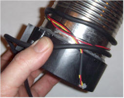
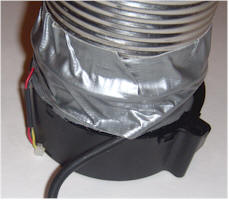
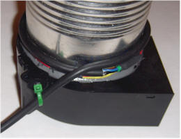
The cable tie looks neater but the important point is to avoid pulling directly on the wires from the fan. The green cable tie passes through a blind hole on the fan that was drilled all the way through. Add some feet to the bottom of the fan so that it can stand vertically. Rubber feet will keep the assembly from moving around due to the fan's vibration. Secure a piece of speaker grill or dusting cloth to the open end of the can with a heavy rubber band:
The black cloth in the picture is replacement speaker grill cloth. Other materials to try include, thin dust cloth, nylon mesh (stocking, tights, etc), porous fabric, open cell foam, and paper from a "HEPA" air filter. Plug in the fan and verify that it pulls air through the filter. That' it! Also see another accumulator design.
The first experiment is to verify that radon daughters are being collected. Here are the steps:
Turn on the fan with the filter facing up and let it run for an hour or two, preferably in a basement room or a room with little air flow and sheetrock or concrete walls, foundation, or countertops. An attic might be a poor choice! Connect the ion chamber to a DVM and turn on the meter. Make an initial meter reading and record it on paper. The reading should be just a few tens of millivolts. Now, unplug the fan and tip the collector over to the horizontal position. Depending on the location of your can on the fan motor, you may wish to add some rubber feet to keep it steady when in a horizontal position. Move the end with the collection cloth as close to the end of the ion chamber as possible without pressing on the foil with significant force. If all is working properly, the meter reading should climb for several seconds and settle out at a significantly higher reading, indicating that radioactive material has collected on the collection cloth. Well ventilated homes may have few radon daughters in the air and it may be necessary to repeat the test in an older building with lots of masonry, or in a basement. Try remote areas of the building where there is little airflow and rock-based building materials like exposed cement or sheetrock. Basements in some parts of the country may require the meter be switched to a less sensitive range!
If all goes well, some radon daughters should have been detected as an increased voltage reading. To proceed, a simple set of experiments could be to try different collection materials to find the most effective. Thicker materials like ordinary paper towels will collect more efficiently but the airflow is greatly reduced. Thin materials will have greater air flow, but may let the radon daughters slip by. The best choice of filter materials may not be obvious.
Once the system is working reliably, several experiments are possible:
Using a timer or clock, plot the meter reading vs. time after the radioactive filter is placed against the ion chamber foil window. The radiation will drop exponentially as the various isotopes decay. Find the point where the meter reading has dropped half way to the background reading and record the time. This time is the approximate average half-life of the collected isotopes.
Run the fan in different rooms or other locations for a specific time, perhaps an hour, and measure the resulting radiation. Different locations are likely to exhibit different levels of radiation due to different levels of radon gas. Can you map the levels and make an educated guess as to the source of the radon? How does the radon level vary with time of day in the different locations?
Visit old buildings, caves, etc. with your accumulator and detector. A hefty 12 volt battery will be needed for running the fan for extended periods. Remember, the radioactivity on the collection cloth decays quite rapidly, so you don't have a lot of time from when the collector fan is turned off to when the measurement is made.
What is the effect of lighting a stick of incense in a room that measures a significant level of radon? My experiments along those lines were surprising. Plot the effect vs. time. For continuous measurements, try pointing the filter cloth directly at the aluminum foil window, but leave a gap of about 0.2" or the thickness of a piece of corrugated cardboard. Plug in the fan and let the reading settle for an hour. The gap allows air to sneak in around the edges so you can plot the radon level continuously. The more advanced experimenter could replace the voltmeter with a computer data taker for automatically making plots. But there is nothing wrong with the manual labor approach!
How hard is it to reduce the radon level in a room? Plot the radiation level before and after ventilating the room. It may take several hours for a small fan or open window to make a noticeable effect. Radon has a half-life of 4 days. So, a tiny fan that replaces the air in a basement in 4 days (that's pretty slow) should cut the radon significantly. Design a heat exchanger using ordinary aluminum vent pipe to save energy when pumping fresh air into the building. A 3" pipe supported by cardboard rings inside a 4" pipe might be the ticket. The outside of the 4" pipe would need good insulation. Outside air would be drawn in via the 3" pipe, approaching the temperature of the surrounding air in the 4" pipe as it goes. The 4" pipe would lead outside and air from the house would approach the outside temperature as heat is exchanged through the wall of the 3" pipe. Since the air coming into the room is already near room temperature and the air going outside is near the outside temperature due to the heat exchange, the head exchanger greatly reduces the energy cost associated with bringing fresh air directly into the house. The 3" pipe should extend a few yards past the ends of the 4" pipe on both ends so that the same air isn't simply travelling in a circle.
Let the collection unit remain off for a day or two. Place it facing the ion chamber, leaving the gap for air flow, as described earlier. After the meter reading has settled, turn on the fan and plot the radiation level vs. time. The reading should climb over about an hour period and eventually flatten out. This plot illustrates a process known as equilibrium. At the beginning of the plot, little radioactive material is on the filter so there is little decay occurring. But as the radioactive material builds up, usually at a constant rate, the amount of decay occurring on the filter increases; the more radioactive material there is, the more likely there will be decays. Eventually, the increasing rate of decay equals the rate of accumulation due to the air flow. This balancing act is the equilibrium point. The curve will have an exponential shape.
Coffee can, baby formula can, cookie tin, about 4" diameter and 5" tall. Chambers can be made in all sizes and shapes. You may wish to remove the insulating coating of plastic on the inside walls but I've found it to be unnecessary, and it does block alpha radiation from the steel of the can. An uncoated aluminum can is best, perhaps one from a canister set.
Internal wire: 22 AWG Buss wire (.025") (Radio Shack 278-1341 is 24 AWG). Copper wire is less "springy" than most other metals so it doesn't vibrate as badly when the chamber is bumped. A moving wire will cause the reading to bounce around a bit.
1/4" hole for RCA connector, RadioShack phono jack: 274-346. Feel free to use other connector types or no connector at all, simply passing the wire through the hole.
Grizzly H5890 Repairman's Taper Reamer or similar. This is a handy tool but not necessary. A ragged hole made with a large drill bit will work, too.
Large rubber feet, RadioShack 64-2342. Those little rubber furniture bumpers are fine, too.
Darlington transistor, MPSW45AG (mouser.com) or TN6725A (Jameco.com). Other modern NPN darlington small-signal darlington types will work fine, but avoid power types.
30 AWG "wrapping wire," RadioShack 278-503. This is thin wire that is easy to use and bends easily. Stiffer wire might pull on the transistor with too much force.
Battery Snap, RadioShack 270-324.
Optional 1k resistor, RadioShack 271-1321. The value isn't critical. Even a value as high as 100k should work fine.
Epoxy, GORILLA Brand available at Home Depot or any 5-minute type.
Radon Daughter Collector:
Squirrel Cage Fan: CF-339 from All Electronics Corp. (www.allelectronics.com). Other types are fine. Computer case fans can also be used to make a collector.
12 volt power supply: PS-1270 from All Electronics Corp. (www.allenectronics.com). Any power supply that can run the fan is fine.
Speaker grill cloth: https://www.amazon.com/Speaker-Grill-Cloth-Black-Yard/dp/B0002ZPLM0 Substitutes are fine, including thin dusting cloth, nylon hosiery material, or other cloth that will allow for some air flow.
Pipe clamp: Found in any hardware store. The aluminum foil window may also be taped on with electrical tape, but make sure the foil is snug against the lip of the can so that it makes electrical contact. The clamp will allow the foil to be easily replaced with screen for detecting air ions or alpha particles.
Two difficulties move this project to the Deep End section of the page. The photodiodes must be in complete darkness yet exposed to beta particles (if desired) and the the circuitry must be electrically shielded. Both can be difficult.
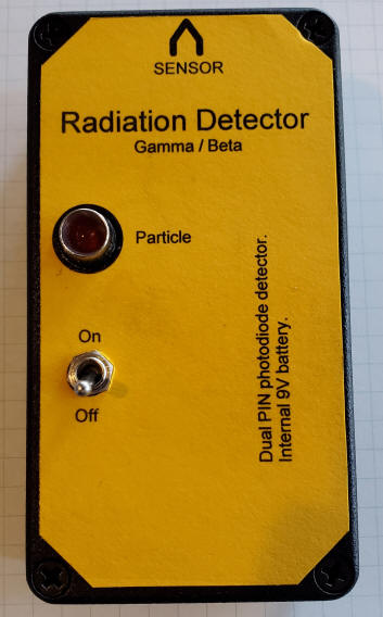
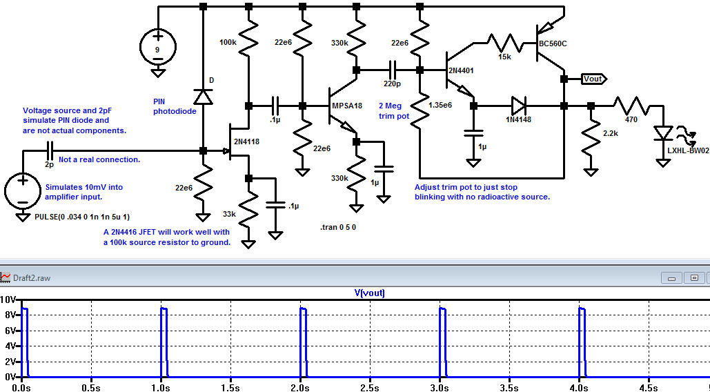
This radiation detector uses two tiny PIN photodiodes in parallel (shown as one diode in the schematic). Using two diodes gives twice the collection area and this detector will flash every few seconds for a radioactive lantern mantle and flash rapidly for a fairly hot piece of pitchblende. The circuit is simulated in LTSpice. When a gamma or beta particle hit one of the photodiodes a small current pulse flows, developing a few millivolts across the 22 megohm on the gate of the JFET. A somewhat larger but far lower impedance pulse appears on the drain and it coupled into the second amplifier stage. The last two transistors form a triggered flasher circuit with an adjustable threshold (two megohm potentiometer). That potentiometer is adjusted until the flasher stops with the unit assembled (complete darkness and maximum shielding). There's a fine line between the circuitry noise and the smaller pulses so a fine adjustment will give more flashes. The more experienced hobbyist may wish to add a micropower, low dropout 8 volt regulator to stabilize that threshold setting but turning down the sensitivity a bit is adequate. Try adjusting the 1.35 megohm in the Spice simulation to see the circuit start free-running for a higher value or to become less sensitive to the pulses at the input for lower value. The "flash" circuit can provide more current to power a small piezo or magnetic speaker but that hole must also be light-tight. When not flashing the LED current consumption is about 50uA. So accidentally leaving the unit on for weeks won't run the battery down unless you live near Chernobyl.
The circuit may be constructed in any way; it's not particularly fussy. But note that I had to use opaque potting compound on the back of the panel LED because light was sneaking in. The photodiodes are glued to a piece of thick, black paper that was tested for opaqueness. (Test your window material by shining a bright LED penlight through the material. If you see any light at all coming through in a dark room, it's not good enough. I once had a sheet of very thin opaque plastic but it's nowhere to be found. Junk like that is worth keeping! The seemingly opaque epoxy on the back of the diodes isn't opaque enough and I had to cover that area with Gorilla brand black tape when operating the unit with the lid open.
Notice I hooked the negative battery wire to the other switch terminal; that's just for support, basically a free solder lug. The solder lug on the board connects the case to the circuit ground and the bolts have insulating washers to avoid shorting circuit traces to ground.
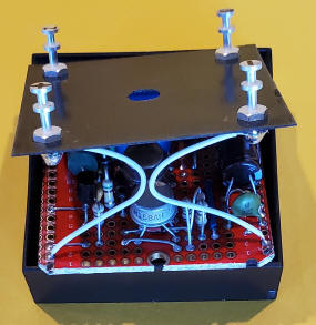
The Hammond case seems to be quite dark inside when the lid it tightened on. I cut a rectangular hole for the photodiodes seen below and I glued the paper over the hole on the inside. Then I wondered how I would locate the diodes! I discovered two rare-earth magnets I have just fit in the hole I cut; I do get lucky at times. So I just drew a rectangle around the inside magnet then glued the diodes into place with super glue (after wiring them in parallel and adding wires). I followed the super glue with the gray epoxy. I used a good marker to blacken the interior walls of the cutout just for looks. There are markers that are more permanent and more black than the typical "permanent" marker. The last photo below shows how I paralleled the diodes for a different project.
It probably isn't the smallest and it isn't really a Geiger
counter (no Geiger tube and it doesn't count) but this really small radiation
detector flashes the LED every time a particle of sufficient energy strikes the
tiny PIN photodiode. The small detector gives about 1 pulse per second with a 2
mR source (using an old fallout shelter Geiger counter and test source as the
reference). This sensitivity is enough to determine if a lantern mantle is
radioactive or a mineral sample is uranium. Most importantly, its small size
makes it inconspicuous! A typical thorium lantern mantle gives about one flash
every two seconds. Thoriated welding rods give a blink about every 10 seconds
and weak Vaseline glass marble gives only one count every 45 seconds so the
detector becomes impractical for the weaker sources. A larger PIN diode is the
simplest way to improve the sensitivity.
The circuit is designed to consume virtually no power so that the detector can
operate for long periods without a power switch. The total current drain when
the LED is not flashing is only 3 uA, giving an operating battery lifetime for
the wimpy type 10A (30mA-Hour) of over a year. The random flashing of the LED
due to background radiation might shorten that lifetime. A regular 9 volt
rectangular battery would be hardly affected.
When particles hit the PIN diode, tiny positive pulses appear on the gate of the
2N4417. These pulses are amplified by the 2N4117 and the MPSA18 and applied to a
two-transistor monostable lamp flasher. The 2N4117 is biased by selection of the
1 megohm resistor in the source such that the drain is at least a couple of
volts above the source. The drain is DC-coupled to the MPSA18 and it should have
a couple of volts from collector to emitter, too. The actual values aren't
particularly critical as long as there is a little voltage across the first two
transistors; the pulses are pretty small. The 2N4401 is biased by two, 62 megohm
resistors connected in series and a 3 meghom to ground so that the flasher
circuit is on the verge of flashing. If the 3 megohm is too large, the LED will
flash constantly and if the 3 megohm is too small, the circuit will not be
sensitive. Other high value resistors may be used but the values should be well
above 1 megohm and the ratio should be chosen such that the flasher is easily
triggered by the amplified pulses. The flasher doesn't draw significant current
when it isn't lighting the LED so the quiescent current is due to the first two
amplifier stages and is only about 3 uA.
Certain precautions must be observed to make a working unit. First of all, the
PIN diode is extremely sensitive to light and it must be kept in total darkness.
I even had a problem with light coming in through the body of the LED even
though it was mounted in a separate compartment! I eventually painted the back
of the PIN diode with black "liquid tape" and added an internal light shield.
The circuitry is also ridiculously sensitive to electric fields and the
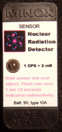
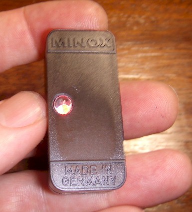
circuitry must be shielded. I decided that an old Minox spy camera film box was
the container to use for a variety of reasons having nothing to do with good
engineering! It is light tight but it provides no electrical shielding. The
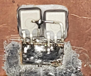
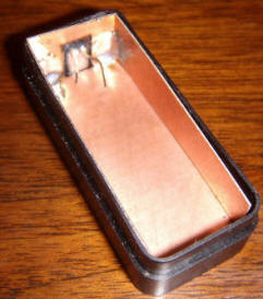
first step was to glue the PIN diode to one end of the case and to add internal
shielding in the form of thin copper circuit board material. Solderable metal
foil would also work.
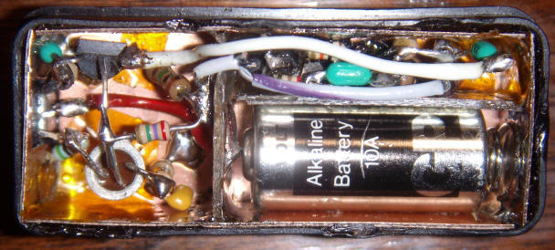
The construction technique could be called the "ship in a bottle" method. No kidding; the construction of this gadget required a lot of dexterity! The battery holder was constructed first, using part of a spring from an AA cell battery holder and a piece of PCB material for the other end. The PCB material forms the positive connection and was made by etching a pad in the middle of the board with an abrasive cut-off wheel and drilling a hole in the middle of the isolated land for the red wire. The solder holding the red wire forms the positive terminal for the battery. Once the battery cavity was made, it appeared that the flasher portion of the circuit might fit in the small cavity directly above. And it did, just barely. This location seemed good since light can come in via the LED body. The PIN photodiode is to the left in the photo above and the FET and MPSA18 are in the same cavity. Not shown is the black "liquid tape" that I dripped on the photo diode and the two wires coming through from the flasher section to block more light. Also, an electric shield was added to completely shield the electronics by adding a metal plate above the electronics with a wire connecting it to ground. This shield is held in place when the lid is installed. The amplifier is so sensitive that the tiny exposed part of the PIN diode picks up electric fields. The unit will not operate properly near strong electric fields.