

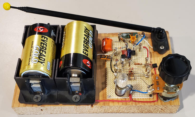
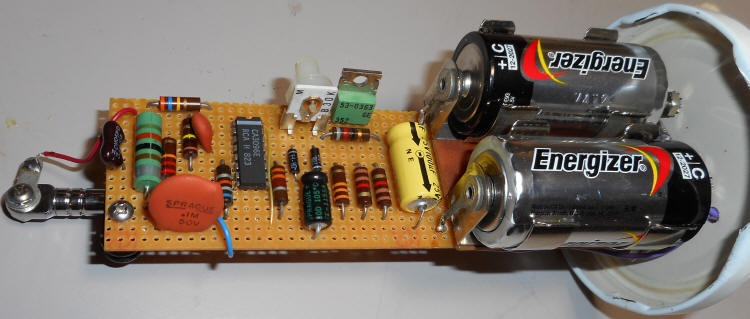
This lightning detector circuit uses a single inductor tuned circuit to receive static pulses from lightning at a frequency near 200 kHz. The amplifier is micro-power and the whole circuit draws only about 200 uA from two alkaline D cells, hardly denting the shelf life. The flasher portion of the circuit is similar to the earlier versions and the prototype is built to make the wiring easy to follow in a photograph.
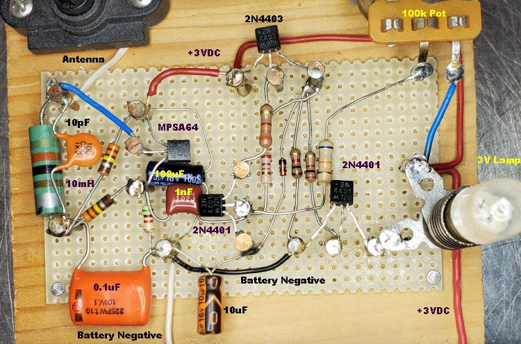
The 150k resistor in the base of the 2N4401 is replaced with a series combination of a 68k resistor and a 100k (or greater) potentiometer in the breadboard above to add sensitivity control. Simply adjust the potentiometer until flashing just stops for maximum sensitivity. The receiver will only work well outside or near a window and modern homes often have interfering electronic devices. For more sensitivity a few yards of antenna wire could be run out a window but connect a 47 pF capacitor in series with the wire at the detector end; a long antenna can lower the receive frequency quite a bit. Also, connecting a good ground will improve the sensitivity; even a metal plate or sheet of foil under the unit will make a difference when connected to the battery negative. Keep the unit away from electronic or electrical appliances and wiring for best performance.
I've used a 2 volt lamp in the prototype ("optional 3 volt device" in the schematic); I just like them! But a bright LED will deplete the battery much more slowly if lightning storms are frequent. Or you can have both.
The construction technique was chosen to make it easy to follow the wiring. Normally, the leads would be stuck through the holes and wired on the other side of the perf board. I used the perf board simply as a guide for copper nails driven into a pine board - strictly to make it easy to see all the connections; there's no other reason to build it this way. Or one could use just nails and wood for the assembly. The copper nails from the home improvement store solder easily, by the way.
A common mistake is to select a 10 uH choke instead of a 10 mH.
The large green choke in the photo is typical of the size and markings to
expect. Color bands are brown, black, orange (10,000 uH). A wide silver band
often indicates the beginning of the color code on molded chokes. Other
experimenters have had success using 10mH chokes intended for power supply
filtering. Some of the other parts in the prototype were chosen to make it easy
for the beginner to see the values. For example, the large 0.1 uF "orange drop"
can be a tiny ceramic type. Parts may be in odd positions, too. The orange 10 uF
is twisted to make the markings visible and other parts are oriented to make
viewing easy. Note the 68k lead is above the diode and 1k resistors; it must not
touch. It's not a fussy circuit so you can build it in a more traditional and
compact way.
The parts are not particularly critical. The darlington PNP transistor may be a
different number, as may the other transistors. The diodes can be any silicon
switching diode, like the 1N4148 (or probably any orange one you have). An amber
LED with a 22 ohm resistor draws about 30 mA with fresh batteries. Vary the
resistor to achieve the desired LED current for other colors (connect the LED
and resistor to the battery through a current meter to select the value). The
output transistor can sink several hundred mA, so several LEDs or other loads
may be connected in parallel. The head from a cheap LED flahslight that uses two
cells will be really bright! The pulse is pretty short to save power and for
quick response, but for longer pulses, increase the 10 uF capacitor value. You
might want a longer pulse to flash a 3 volt incandescent bulb (my favorite).
Actually, I'm using a 2 volt bulb and it's really bright, even with this short
pulse! I have lots of them and I'm sure I'll need to replace it fairly often.
(Um, it's been years since I first wrote that - it's still fine.)
Marcos in Brazil made a video of his detector.
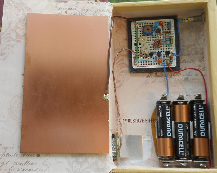
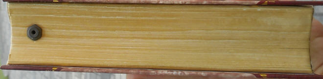
Here's a version I built into a "fake" book I found at an art store. The copper PCB is connected to the circuit ground to act as a counterpoise for the antenna, increasing sensitivity. The lightning bolt was cut with a sharp knife then filled with blue-dyed epoxy. The antenna connects to the dark pin jack. I used a cheap flashlight head for the LED - I used too much blue dye in the epoxy so I need a bright flash! I need to find a way to title the book, "Stormy Weather."
 |
 |
 |
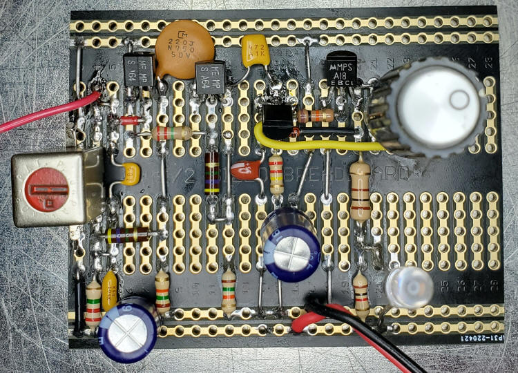
Here's another version that replaces the darlington transistor with a compound transistor consisting of a PNP and NPN transistor. Ordinary small-signal transistors will work great but this change also allows the use of the venerable CA3096 transistor array. The 10 mH resonates with about 250 pF around 100kHz, a quiet frequency now that Loran-C is gone. But try much less capacity if you think you're getting interference from appliances in the house, as low as 10pF as done above. The antenna adds up to 10pF, too.
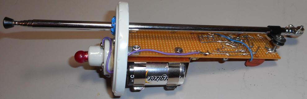
Since the CA3096 is pretty ancient I decided to use "period" parts for the rest of the components:

I then decided it needed to flash an old "Mazda" (GE trade name) 3 volt light bulb but the transistor in the array can't handle the current. I added an old green (PNP) GE power transistor to handle the additional current. Good design practice would suggest adding a 1k pull-up resistor at pin 9 or the power transistor base to plus but it's really optional and it didn't fit nicely. Some of the resistor values differ from the schematic but most aren't critical.
I borrowed Lennie's jar packaging approach so that the old components would be visible (otherwise, what's the point? : )
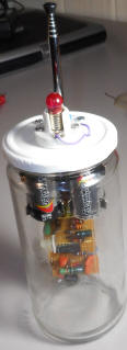
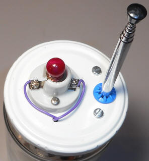
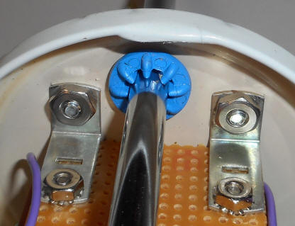
I placed the batteries near the top and secured one end of the battery holder directly to the lid for strength. A loopstick antenna may be used with the designs above. The inductor is replaced with a tuned loopstick or solenoid coil. See https://techlib.com/electronics/lightningnew.htm#Magnetic for a low frequency example but a traditional crystal radio loopstick resonated to just below the AM band (to avoid radio stations) will work, too, and may be less susceptible to interference from low-frequency emitters in the house.
Here's a detector with a little more gain and that operates well just below the broadcast band, around 450 kHz, but with about the same complexity as the earlier designs. The darlington transistors can amplify at the higher frequency while consuming less than 100uA per stage. The higher frequency is helpful in homes and businesses with lots of modern appliances, often powered by poorly filtered switching regulator power adapters. Such appliances can make a mess of the low-frequency band but the noise must be down by the bottom of the BCB to satisfy regulatory agencies and consumers. So let's cozy up to the bottom of the BCB. The antenna tank has higher Q than previous designs since there might be powerful AM stations near the bottom of the band, too. I've aimed for 455kHz or lower (the antenna and darlington contribute to the capacitance). If you live in an area with a strong station near the bottom of the band you may wish to use an AM radio IF transformer in place of the 1mH and 100pF; just use the higher resistance winding and choose one with the little capacitor in the bottom. I modified mine to use an AM oscillator coil transformer (the one with a red adjustor and no capacitor) by changing the 100pF to 680pF; that landed mine at 440kHz.. I do have a strong station nearby at 590kHz so the mod isn't a bad idea. I left the adjustor in the middle but gently bottoming it out would reduce the frequency even more. Frankly, I don't think the AM station was a problem with the 1mH choke but I like the higher Q (about 50). You could also just use a small inductor and larger capacitor but many experimenters only have inductors for switching power supplies and those often don't have good Q. An IF transformer does.
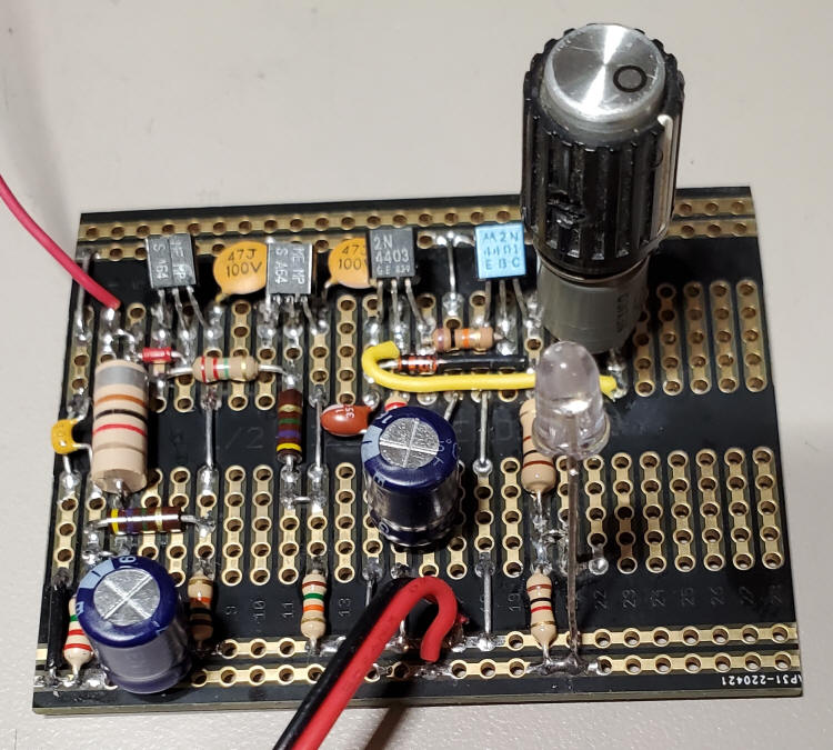
The original prototype is to the left. Note the lower gain 2N4403 and 2N4401. Somewhat better sensitivity will result using the higher gain transistors in the schematic and the photo to the right, Note the BC560C is flipped due to the different pinout. I used a small knob for the photo but I'd use a larger diameter knob to make fine adjustment easier. The IF transformer mod is to the right. Note that I soldered the can to traces used to pass +4.5 volts from one side of the board to the other. This makes the can "hot" but that doesn't matter. I wanted the extra mechanical strength. The unused pins are hanging off the edge and I'll cut them short. Make sure to use the high resistance winding and you may need to cut off a middle leg if the coil is tapped. An IF transformer would not require the capacitor since one is built in. But make sure you are not using an FM or TV IF transformer and double-check that you are using the higher resistance winding.
If you can adjust the pot to be on the verge of flashing but don't seem to have sensitivity you may have interference and some fiddling may be needed. A simple approach is to tighten the adjustor (gently-they're fragile) and increase the 680pF cap to move down the band. A more involved approach would be to find out what's actually happening. An adequate place to probe is the collector of the first darlington, using a X10 scope probe. I clip a scope probe to that convenient wire jumper (sixth row from the left). Connect the battery when testing, you need the darlington functioning. Don't connect your generator directly; just use a clip lead tangled a little with the antenna and keep the signal at the collector small or distortion will skew the results. Determine the bandwidth by finding the peak (between 400 and 500 kHz) and then the 3dB down point on either side. The bandwidth is the difference frequency between the 3dB points and the Q is the peak frequency divided by that bandwidth. A molded choke will have a Q around 20 and the IF can around 50. Project the performance at the BCB assuming the signal is dropping 6dB per factor of 2 (octave). Example: you get -3dB at +9kHz above the peak then assume 6 more at +18kHz (2 *9) for -9dB then assume 6 more at +36kHz (2*18), etc. You can try to measure it but the signal gets very small and often bottoms out due to the generator being too nearby; as you adjust the frequency further the amplitude stops dropping.
Here's a great display for the lightning detectors with the ability to flash an incandescent bulb (several hundred mA). That's a large LED lightning bolt lamp I found on Amazon. (Watch out; there's a smaller, identical-looking bolt (just a few inches tall) but I highly recommend the larger one that's about 30cm.) I removed the battery holder and added a 6.8 ohm resistor to limit the current (it seems to like around 300 mA). It's on a wall in my basement lab and I have to say it's pretty spectacular when a storm comes. The bolts cost about $16 IIRC.
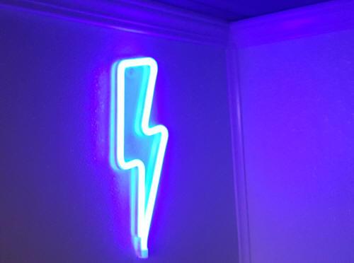
By the way, don't plug this bolt into your modern USB port on your computer. I'm convinced the wiring is incorrect with the USB 5 volt line connecting directly to the LEDs (and not through the 10 ohm resistor in the battery compartment). A higher-current USB output can therefore force too much current through the LEDs destroying the bolt quickly. Hopefully the manufacturer will discover the error. Note the reviews by unsatisfied customers due to premature burn-out. Older USB ports will current-limit around 500 mA but that's a bit high, too. Update: I just built another one with a new bolt and the resistor was wired correctly; I guess they found the mistake.
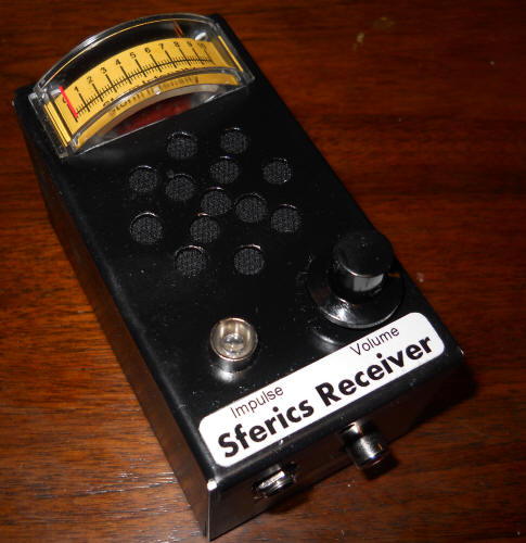
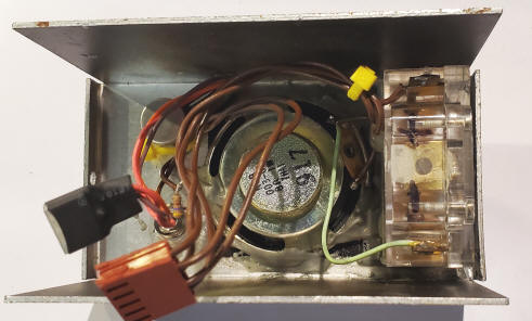
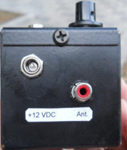
"Sferics" (also spelled "spherics") is short for atmospherics and refers to the crackling static in a radio produced by lightning. This receiver is tuned to an unused portion of the LF band and provides enough sensitivity to detect lightning activity for hundreds or even thousands of miles. Best performance is achieved with an external antenna, but just a few yards of insulated wire is sufficient. A short whip mounted on the unit will work fine for picking up local storms.
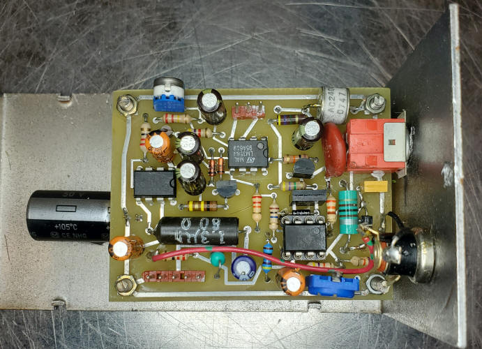
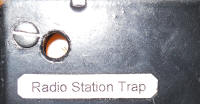
Starting to the left, a trap may be added by resonating a 470 uH or 1 mHy choke with a selected capacitor to eliminate a strong AM station when using an outdoor antenna, especially an amplified antenna. The trap isn't usually necessary with a short antenna. (I like faint station bleed-through, simply to let me know it's all working properly.) The 220 ohm resistor between pins 2 and 7 of the TL592 has been changed to a 200 ohm (or 500 ohm) pot to allow for the use of a short antenna or an active outdoor antenna. The blue pot to the bottom, right is the gain pot and one leg had to be bent towards the other to fit into the two holes that were for a molex connector. A 33 ohm resistor is in series with the 10 uF from pin 1 to 8 on the LM386 to reduce instability when the volume is turned up high. This audio amplifier has gain at the received frequency so feedback is possible. The 47 ohm resistor, 1/2 watt resistor wound with 30 turns also reduces unwanted feedback. (The resistor is 1/2 watt just for the diameter.) Feedback is also possible at low frequency so increase the 100uF across the power to 1000uF (the black cap sticking out from under the PCB to the left) if you get "motorboating."
Use a good ceramic capacitor for the 2.2 nF capacitor; a
couple 1000pF, COG/NPO caps in parallel would be a great choice. Use a good RF
capacitor; this value also "shorts out" higher frequency stations and it's best
to mount it right at the pins of the amplifier. The values shown receive static
at about 300 kHz, a higher value than my original receiver to dodge noise from
cheap electronic ballasts throughout my neighborhood. Keep the frequency below
about 350 kHz or you will have problems with AM band interference. That's the
purpose of the 330 ohm resistor, to give the tank capacitor something to work
against when rolling off higher frequency stations, especially strong FM
stations.
The 1N5711 detector is a biased detector with a twist. The
detector has a long discharge time-constant that gives the output a ramp-like
response to lightning pulses, with the length of the ramp being proportional to
the size of the pulse. That causes the first LM358, acting as a comparator, to
output a pulse with a width that is proportional to the received pulse height.
The detector's amplitude-to-pulse width response also gives more powerful
strikes a deeper sound, making it easy to tell what's happening simply by
listening. You hear a "tick" for weak pulses and a deep "thunk" for big ones.
Those pulses drive a lamp flasher and another op-amp averaging circuit for
driving a meter. The tendency of the lamp to flash is easily modified by
changing the 10k pot to ground on pin 2, with a lower setting making the light
more sensitive. The 22k resistor determines how much each pulse affects the
meter reading, and the 10 megohm determines the window of time that is averaged,
lower values giving a faster response.
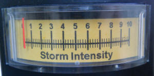
The schematic uses a 10mA current meter, but a voltmeter would also work fine.
Expect about 3 volts at pin 7 when the lightning is "pegging" the meter circuit.
Here's a quick video of the unit working.
The LM386 needs care to prevent oscillation, because it has gain in the
frequency range of the receiver. First of all, note the 4.7 nF at pin 3 is a
little larger than normally seen, and the addition of the series 4.7k makes sure
there is roll-off even when the volume control is all the way up. It isn't a bad
idea to increase the capacitor to 10nF if instability is encountered. Also, the
output stabilization network is modified to block RF from getting into the
speaker wires. I used a commercial part but you can simply wind 30 turns of
enamel wire around the body of a 1/2 watt, 47 ohm resistor, or wrap four or five
turns through a ferrite bead and connect that in parallel with a 47 ohm
resistor. It would be a good idea to keep the speaker away from the input
circuit and to twist the speaker wires together.
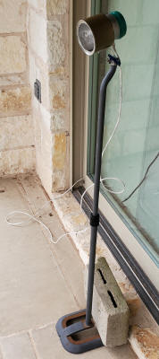
An outdoor antenna gives best results but it only needs to be a couple of meters
long. Any more range and the unit would be excessively sensitive. In fact, be
prepared to lower the gain of yours; it's not that great to hear every bolt that
happens in the country. A ground wire to a cold water pipe is wonderful when
practical. I'm currently happy with an indoor wire antenna stretched across a
sliding glass door feeding about 3 meters of coax and a ground wire from the
case to a piece of test equipment on the same bench (basically connecting the
case to the AC power ground).
To see earlier versions of this project and the original PCB design visit https://techlib.com/electronics/spherics.htm .
This simple device is in the "Deep End" section due to the americium. One needs to be careful with that stuff. Don't try to remove it from it's little ion chamber; put the whole chamber in there. I soldered a solder lug to the chamber's wire and mounted it under a bolt. Some chambers have the americium bit mounted in a metal clip so leave that intact, too.
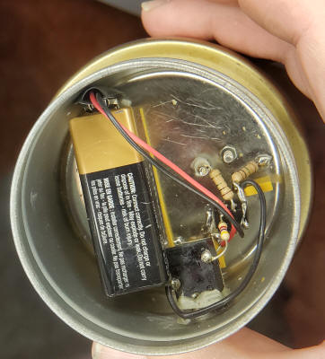
This experiment attempts to use ionizing radiation from an americium pellet removed from a smoke detector to continuously discharge a sense antenna for electric field measurements. As long as the ionization can conduct significantly more current than the bias and leakage current of the buffer amplifier the wire should stay "neutral" and be able to sense a static DC field, or so goes the theory. The circuit is trivial, simply a voltage-follower CMOS op-amp (TLC27L7) running on 9 volts connected to the sense wire through a 1 megohm just for safety (let's call it an "idiot resistor"). A 4.5 volt "artificial ground" made with two 1 megohm resistors biases the can halfway up. The high-value resistors and micro-power op-amp will run on a single battery for years. Other CMOS micropower op-amps will work; a single americium pellet generates up to 100pA worth of ions and a typical CMOS op-amp will have bias current well below that. This time there is no bias voltage on the can except for the artificial ground formed by the two 1 megohm resistors; the ions simply "connect" the op-amp to the sky's field by preventing charge accumulation. Note the can is pointing horizontally but the yard drops quickly so there's plenty of sky visible at that angle. Also note the cement block on the base of the stand; storms are windy, it turns out.
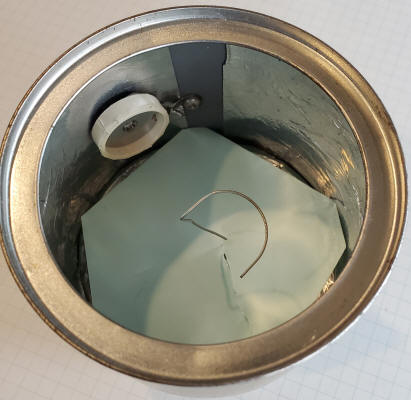
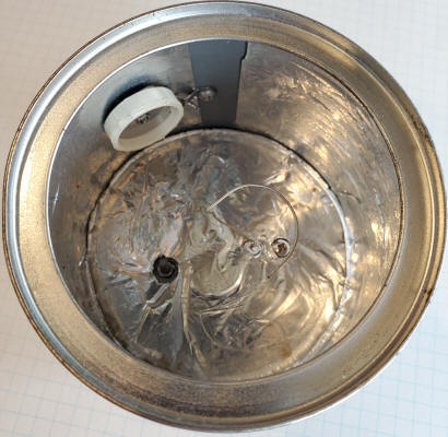
I mounted the smoke detector americium element in an almond can with a pickup wire near the center of the can a little back from the opening. I stuck a piece of paper in there to make the wire more visible; the paper doesn't stay. There's a little half-loop just to give it a bit more capacitance and the wire is soldered to a Teflon feedthru.
I'm using jAmaseis to record the data using a simple PicAXE data taker that sends a serial value to a COM port six time per second, a typical rate used for seismometers. Tell JAmaseis that the device is a "SEP." Set the zero value to the "last value" (at the bottom, left of the screen when it's plotting) to move the line to the zero point (when there's no storm overhead, of course). The circuit is biased to Vcc/2 so the output can swing positive and negative around that value.
I use another op-amp in the house to buffer the voltage (to save the battery in the outdoor unit). It might be better to run the outdoor unit on three AA cells so that the PicAXE can be driven by a buffer op-amp running on the same 5 volts, saving the need for a scaling circuit and/or additional higher voltage power supply in the house. Remember, don't load the outdoor unit much or your battery will go dead quickly so an op-amp follower is recommended.
A cooperative storm came through last night and I got the result below.
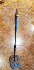
The plot starts out near zero volts where it's been sitting for days and then trends negative as the storm approaches. When the storm was just about to be overhead the voltage dropped significantly and became quite active. Notice how the voltage can stay negative for a long time, illustrating that it really is "DC-coupled." Here's a test accessory consisting of a circular piece of coarse screen on another stand. The screen is connected to a variable power supply to verify that the circuit can continuously detect a steady DC field.
When it was first installed it wouldn't hold it's value but would quickly drift back to zero as though the americium wasn't doing its job. It turned out to be a single strand of spider web bridging the sense wire to the can. There will be maintenance issues with these things! I'm thinking of snapping the almond can's cover on when there's no interesting weather. I use a soft paint brush to remove the cob webs! I hope the americium doesn't create killer mutant spiders.
Another storm system passed through last night:

