
| One Transistor Reflex |
| Two Transistor Reflex |
| Computer Speaker Radio |
| Matchbox Reflex Radio |
| Two Transistor Radio |
| JFET Radio |
| CD4069 Radio |

The reflex receiver uses the same transistors to amplify the RF and the audio independently, effectively doubling the transistor count! Reflex designs were born in an era when transistors cost several dollars each and pressing them into "double duty" was worth some effort. Import laws categorizing radios with two or fewer transistors as "toys" added to the motivation. Today, excellent transistors can be had for a few pennies each, not to mention ICs filled with them and "Boys Radios" with only two transistors are collectibles! But it is still interesting to push for more performance from simple circuits and the reflex receiver is not disappointing.
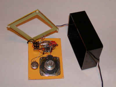
Instead of a loopstick antenna, this receiver uses a coreless coil and an ordinary "telecom" transformer for the feedback signal. (I have a plentiful supply of the PE-64943 (1:2 with taps on both sides - great for experimenting. I can send these to USA addresses. Remove removethis, obviously!) The one part that might be a little hard to get is the MPS-A18; if you must, pick a substitute with very high gain. A Darlington can be made to work but there may be noticeable distortion. The 1N5711 is an ordinary small-signal schottky diode. The circuit passes the transistor bias current through the diode, increasing its detection sensitivity. Here is the schematic:
The antenna coil is 20 turns wrapped around four insulated posts as seen in the photos and shown in the diagram below. I used nylon posts but ordinary bolts covered with tubing would work fine. The dimensions are not particularly critical; those shown happen to fit inside the case I chose but a large coil will receive better. If your antenna tunes too low, remove a turn or two and if it only picks up stations at the top of the band, add a couple of turns. The signal is coupled to the receiver by two turns wrapped right on top of the 20 turns. This winding technique is simple but it has the drawback of having more than desirable capacitance and that limits the tuning range with a standard 365 pF variable capacitor. To get around this limitation, a switch and 100uH inductor has been added as a band switch to allow the reception of the higher frequency stations. This circuit is actually regenerative, too, giving it even more sensitivity. This antenna system tends to give more regeneration at the high end of the band and the volume control (5 k) must be turned down a bit if it squeals.
The output transformer may be a 1k to 8 ohm audio type or even a 12 volt filament power transformer if you have room in your case. Some power transformers sound muffled due to poor frequency response so if your radio sounds like the treble control is all the way down, try changing to a different style of transformer. But don't hesitate to try a power transformer; the best performance I got was with a power transformer, outperforming my smaller 1k to 8 ohm audio type seen in the photos and they are easy to find. (The 12 volt winding goes to the speaker and the 120 volt winding goes to the transistor.) Although I didn't try it, a 6 volt power transformer might work well with a 4 ohm speaker.
The telecom transformer is designed for high bandwidth ISDN or
T1 digital signals and it doesn't have much of a response to the audio signal
but works well for the AM band frequencies. Other similar types should work,
including some pulse transformers and other broadband RF transformers as long as
they look like a low impedance to the audio and behave as nice transformers for
the RF frequency. Try winding your own on a piece of ferrite and experiment with
different turns ratios. It should make a miserable transformer for audio and a
good transformer for BCB frequencies. The windings should have around 1mH
inductance (that's 20 ohms reactance at 3kHz (nearly a short) and 3,000 ohms at
500kHz making for a decent RF transformer. But even a 5mH transformer should
work fine.
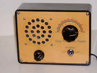
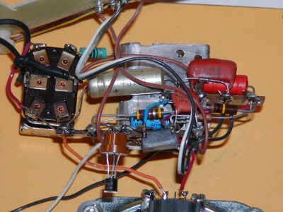
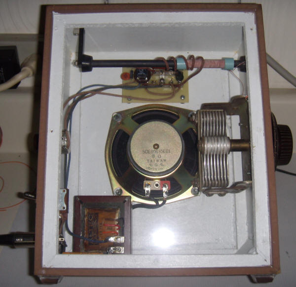
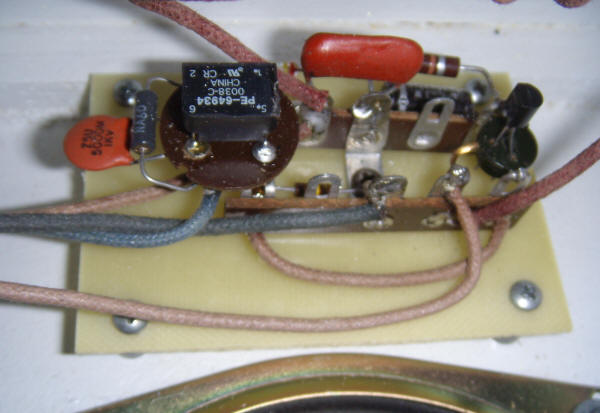
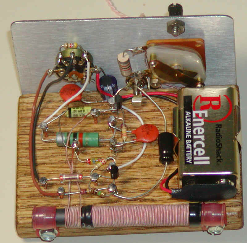
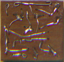
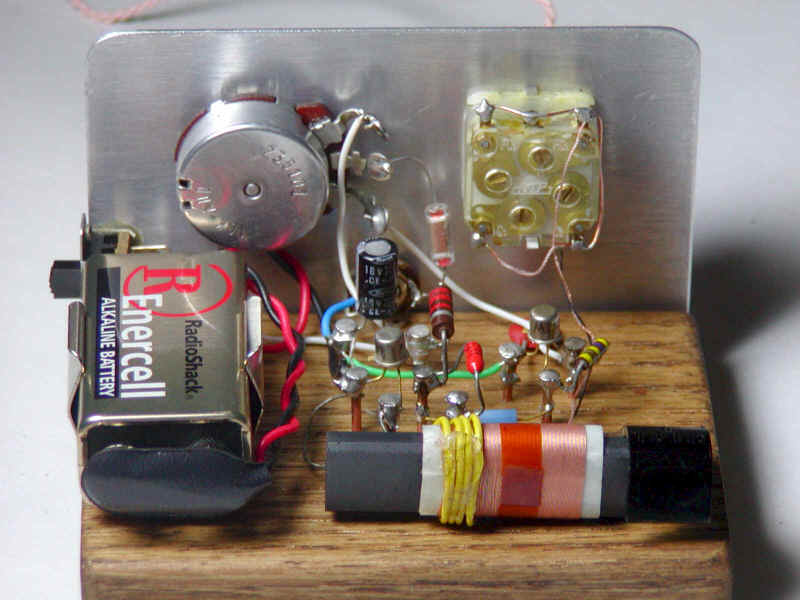
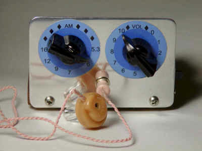
My radio is built into a phenolic box with a clear plastic lid. The legends were
printed on colored paper and glued with spray adhesive to the inside surface of
the plastic. A couple of terminal strips and the terminals of the speaker,
switch and capacitor mount all of the parts. The center of the fiberglass
antenna support was cut out to make room for the speaker magnet. I built the
circuit on an old-fashioned terminal strip. It doesn't look neat but it's quite
mechanically sound:
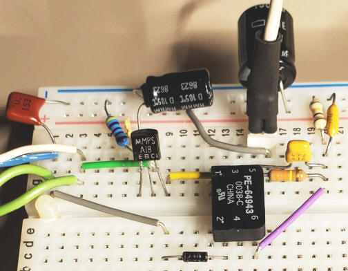
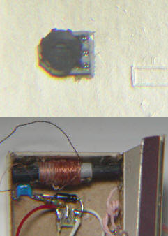
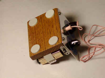
Don't feel compelled to copy the mechanical design exactly! It works just about any way it is made. Here is a photo of a nicely working version I tried on a prototyping system that I am making for my kids seen in the last photo above. I used a socket for the transistor so I could try different types easily; it's not really necessary.
This circuit would make a great single-station radio. Leave out the switch and inductor and replace the 365 pF variable with a fixed value selected to tune the desired station. You might want to add a shunt resistor or trimmer across the 5k pot to limit its resistance to the value that gives maximum volume without distortion.
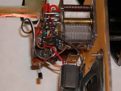
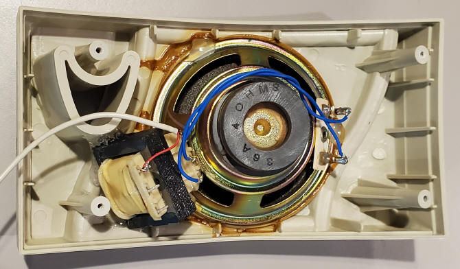
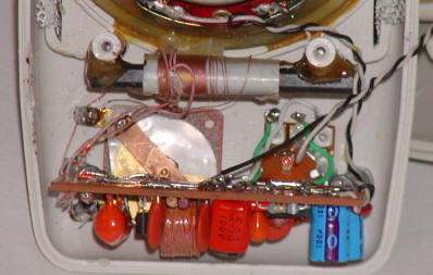
I constructed another version with an emphasis on volume:
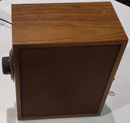
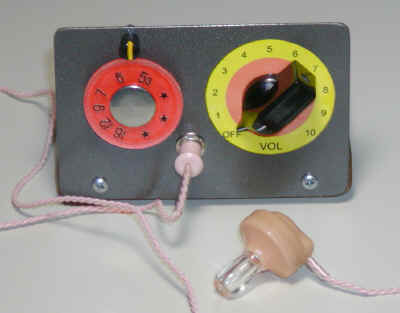
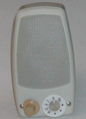
This version is built into an old speaker enclosure and the pressed board back is replaced with clear plastic to allow viewing the insides. One might be called upon to prove that there is only one transistor! From the front, the radio looks like an ordinary brown speaker with a tuning knob on one side and a volume control and power switch on the other. Power is supplied by a 24 volt molded power supply. The original speaker was replaced by a two-way radio replacement speaker that seems very efficient. The audio transformer is a 70 volt music distribution type wired for maximum step-down. The ferrite rod is 6.5" long, held at the ends by rubber feet, and is tuned by an old Atwater Kent variable capacitor. The pulse transformer is mounted on the base from a fluorescent lamp starter and the transistor is in a socket to help make those component's thin, short leads compatible with the clunky solder terminals. The secondary on the ferrite rod is a few turns of hookup wire wrapped loosely near one end of the primary. Playing with the spacing and position gave good performance over the whole band. The variable capacitor tunes the loopstick over the entire band without a band switch. This version is indeed loud and it's fun to show it to other hobbyists who actually appreciate it!
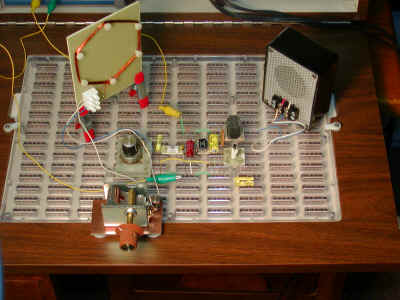
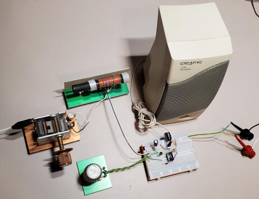
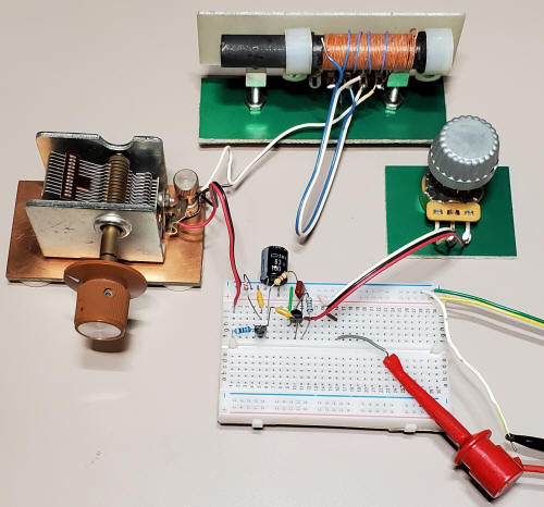
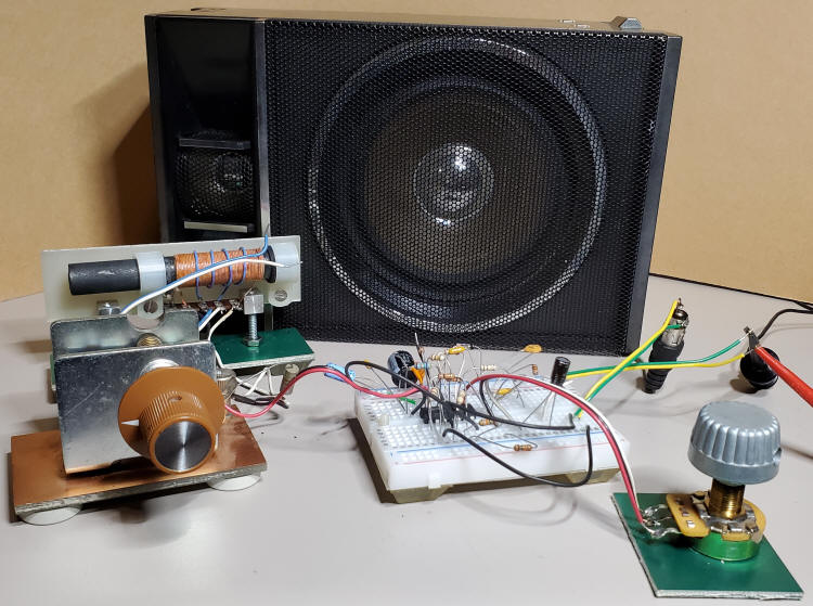
Below is an experimenter's setup featuring the same circuit with easily changed components. The components include a typical "365pF" variable capacitor, a loopstick with a four-turn secondary, a 10k potentiometer, a computer speaker and protoboard for the other components.
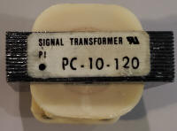
The speaker is an older PC speaker without an internal amplifier. I've installed the bulky transformer inside the speaker's case. Note that the transformer is a Signal Transformer PC-10-120 (120VAC to 10VAC) power transformer. This transformer isn't intended for audio but a test with a signal generator shows it is flat to 6 kHz, plenty for the AM band. My favorite type is the audio transformers used in 70 volt music distribution systems but they can be hard to find. A low voltage transformer like this one is often suitable but some transformers will create a muffled sound due to poor frequency response.
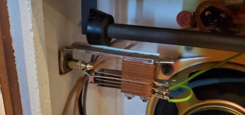
The purpose of this setup is to test ideas. For example notice the PE-64943 (that's different from the PE-64934 used above 43 vs 34 at the end). I'm able to compare the transformers (no difference) and different taps (little difference). I can easily try other transformers, transistors, etc. One interesting discovery: the black boot clip lead to the left connects to a coaxial cable outer shield that passes through the frame of a sliding glass door via a bulkhead feedthru. That shield is therefore connected to the metal frame of the door and the entire door frame becomes an antenna. It works quite well! But it only works if I don't connect the capacitor ground to the circuit common. One could have an external antenna jack that disconnects the capacitor from circuit ground and connects it, instead, to an external antenna jack. I just added it to my big speaker above (see the picture of the jack below. The radio behaves like a commercial radio with the door frame connected!
External Antenna Jack added to the large speaker box version above:
Here is a two transistor radio that really performs! The first transistor acts as a reflex stage similar to the one-transistor reflex radio above except that no RF transformer is used. Instead, a 10 millihenry (not microhenry) choke sends the RF to the diode detector and the audio to the output stage. This simpler approach is not as sensitive as the transformer feedback version but the addition of a simple one-transistor audio amplifier makes this receiver really scream. You will not be using this radio with the volume control turned up full! And you can really pull in stations with a simple loopstick antenna. An amplified speaker from a PC may be plugged into the earphone jack.
 |
  |
The tuning dial has a pointer made with a slotted screw and standoff. The screw and standoff are painted black and the slot is filled with yellow paint to make the pointer. I did not have a 5k potentiometer handy so I just paralleled a 500k pot with a 4.7k resistor which works fine due to the high input impedance of the audio stage. Also notice that I added a 1000uH choke across the tuning capacitor to reduce the loopstick inductance a bit, instead of removing a few turns. The wire is litz but ordinary enamel wire will work well. A small line of glue is on the bottom of the windings (out of view) to help hold them in position. My secondary is more like 10 turns but the number isn't critical. You may also notice that the input capacitor to the amplifier is a .47uF ceramic and not a 1uF electrolytic and the output capacitor is a 10uF instead of a 1uF but these values are not critical. This amplifier has plenty of output for driving an audio power amplifier and speaker.
This is a serviceable radio; I use mine every day.
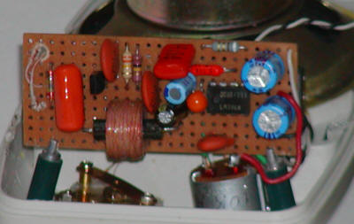
Here is a reflex receiver built into a surplus computer speaker using an LM386 audio amplifier IC. The circuit is built onto a little piece of phenolic perfboard that is secured by wedging the edges of the perfboard into a couple of bifurcated standoffs. The on-off switch is part of the volume control that is mounted next to the tuning capacitor. The loopstick antenna is glued to a couple of plastic posts that are part of the enclosure as can be seen in the photo. The 9 volt battery is located in the C-cell battery compartment with plenty of room to spare. The performance of this simple receiver is quite good, giving a blasting full volume on a couple of stations with no antenna.
Play with the number of turns on the secondary to get the best results; more turns will give more sensitivity but the circuit might become unstable, especially at the low end of the band. Fewer turns will give better sound but at some point the sensitivity will drop off. Three turns make for a great receiver with my version. I had to remove a significant number of turns from the loopstick to make it tune properly with the 365 pF variable capacitor because the loopstick was designed for a significantly lower value capacitor.
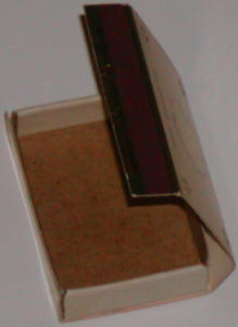
Building little radios into matchboxes is a traditional hobby pursuit and reader Augustin from Romania inspired me to try my hand at it. For my matchbox receiver, I chose my two-transistor reflex receiver with a couple of modifications:
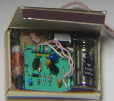
The tuning capacitor is replaced with a varactor diode and potentiometer to save space and the antenna coil is a modified loopstick from an inexpensive AM radio. The circuit is powered by a tiny 10A type 9 volt battery which should last about 30 hours with the 1mA drain. The first step was to choose a nice matchbox. After a trip to the local flea market, I had a jar of "collectible" matchboxes. My favorite is shown below, carefully taken apart and held flat by a plate of glass and then reassembled to form an easy to work in enclosure:
 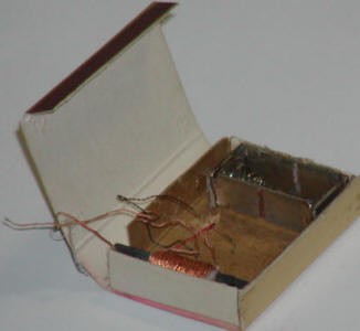 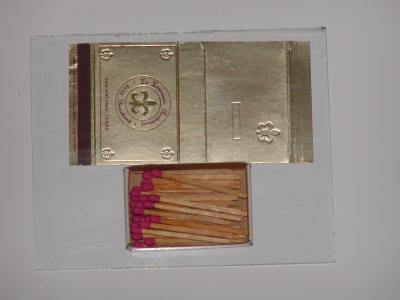 |
Alcohol removed the printing from one side of the box which became the front and the drawer section was glued into place forming the backside of the front of the radio. The new flap becomes the back access door and the striker fits inside the box to secure the flap. A slight taper and notches make this flap snap into position much like the lid of a raisin box. A battery compartment was fashioned from tinned PCB material and the battery springs from the sacrificed AM radio. Note that strips of copper were removed so that the holder would not short the battery. Don't choose a metal foil matchbox for a matchbox radio! The foil can short things out and tends to lower the Q of the antenna coil. Looks good, though. The tuning pot was mounted on the face of the box as shown in the photo. After losing a battery to premature discharge, the foil around the legs of the pot was trimmed away! The tiny loopstick antenna was glued into one end of the box and the electrical tuning components were mounted on a tiny piece of PCB material directly opposite the tuning potentiometer. The circuit layout was done with the free layout software from ExpressPCB and a printout of the design was glued to a piece of "Tropic Jade" laminate for use as a drill guide.
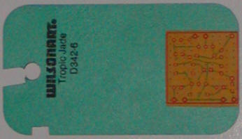
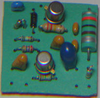
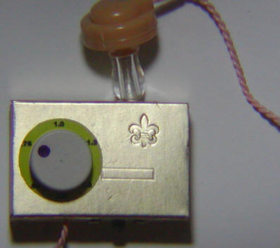
A dental pick was inserted into the holes for wires and component leads were bent around the pick to form eyelets. After a bit of a struggle, a power switch was added and the completed circuit was installed. The sharp observer will note the absence of the more attractive metal can transistors. I had stability problems due to too many turns on the original secondary that I mistakenly attributed to the transistors. If your radio squeals or seems unstable, reduce the 12 turns to maybe 8 or so. A dial fashioned from a plastic foot was glued to the top of the potentiometer, finishing the radio. The radio works quite well for its size, giving good volume for my favorite station; in some parts of the house it is loud enough to need a volume control (just null the signal a bit by rotating the box). I still can't believe these regenerative reflex circuits!
For more examples of reflex receivers see the original page at https://techlib.com/electronics/reflex.htm
Here is a simple radio that was designed to minimize unusual parts; there isn't even a detector diode! The sensitivity isn't as high as the one-transistor reflex but the simplicity is attractive. Strong stations will provide plenty of volume into a crystal earphone or an external amplifier (try an amplified computer speaker). The AM Loopstick was purchased on eBay but the enterprising experimenter can swipe one from the interior of a cheap radio. If the loopstick has more than one winding, use the one with the most turns. Wind 3 or 4 turns near one end of the winding as seen in the photo. The tuning capacitor in the prototype is from an old radio and the little plastic dial was cut down such that it just fit into the back of a black pointer knob. The fit was tight so no glue was needed (a bit of luck). All of the sections of the capacitor were connected in parallel to get the most capacitance for this loopstick.
 |
  |
All the other parts are common. The transistors can be just about any small-signal type. The prototype uses the metal can 2N2222, primarily for looks. Don't leave out the large capacitor across the battery, it provides needed low power supply impedance.
A JFET may be connected directly across the primary winding of a loopstick antenna without loading concerns due to the JFET's extremely high input impedance; the selectivity of the tank stays high. This simple circuit is built on a protoboard using the experimenter's components mentioned above. A J201 or similar JFET provides RF gain to a high-gain detector/amplifier, made with the MPSA18. The audio output can drive a typical speaker amplifier without additional gain. Many JFETs will work in this circuit but adjust the 4.7k resistor value from the drain to plus to achieve at least 6 volts on the drain. The secondary winding is not connected but, as before, connecting a long wire antenna to one end of the secondary winding (leaving the other end disconnected) will increase the sensitivity. The secondary winding acts as a small coupling capacitor.
Many years ago hobbyists had fun trying to realize just about every circuit function with a CD4069 hex inverter for the active elements. They linearize nicely, forming an amplifier with a gain around 20dB at BCB frequencies and higher at audio. They may be treated as low gain inverting op-amps with the positive input conveniently connected to Vcc/2 internally. Just two resistors are needed to set the closed-loop gain. (The open-loop gain is low so the closed-loop gain will be lower than the resistor ratio might suggest but I've even made an effective audio active filter using them as op-amps (see the 24kHz SID receiver.)
The circuit below uses two inverters as RF amplifiers driving a two-diode detector (germanium diodes work well here). The resulting audio is amplified by another gate using two resistors, the 100k to reduce RF feedthru and the 2.2M to bias the gate. Those values don't reduce the open-loop gain much. The volume control pot drives an amplifier essentially working at full gain and an inverter driving another identical high-gain amplifier. The out-of-phase signals drive the transformer with a large AC voltage, a configuration often called a bridge connection. The transformer is built into the large "boom box" speaker and is a Realistic 32-1031 audio line transformer. This speaker was found to produce more audio for a given signal than others I have. The line transformer (used for70-volt music distribution systems) matches the 4 ohm speaker to the circuit using the "0.62 watt" tap efficiently. It works so well I had to add the volume control! An efficient speaker in an enclosure is hard to beat for these simple circuits; it's free gain and makes quite a difference. As before, an external antenna may be connected to the unused secondary on the loopstick (if you have one) or simply connected to pin 13 through a 10pF capacitor. Notice that the first inverter is biased in a way that keeps the input impedance very high, not unlike the JFET circuit above. Connecting the 470k to pin 13 would reduce gain and Q of the tank. I'll have go build a nice version of this thing; it gives plenty of volume with only a wimpy CD4069 driving the speaker. A few experimenters as old as I will appreciate it!
Note: add a 33pF from pin 5 to pin 6 (across the 22k) to prevent instability. That stage has a gain of only one so compensation is a good idea. The prototype didn't seem to need one but it won't hurt.